Wednesday, December 14, 2011

Making The Window Latch Steel Link

 This part is the dog legged link which is attached to the 2 brackets on the door.  The only reason I can see for it being made of steel is the bend in it which allows it to clear the top of the door when the window is open. This part is made from .050" steel.  To get the same strength from aluminum it would have needed to be much thicker.  Thicker aluminum would have been much harder to form even without the dog leg bend.  It is probably mild steel but I have some .050" 4130 steel so that's what I'll use.
 To form this part I need something stronger than hardwood.  Instead I'll use a piece of mild steel.  The inside of the channel shape is 7/16" wide and Tractor Supply only sells 1" x 1/2" bar stock.  The easy solution would be to mill a piece to thickness but I don't own a mill so I used the band saw to cut off about 1/16" and used the belt sander to finish it to thickness.  The 2 pivot holes were than drilled and tapped to use 3/16 fine thread bolts to hold the blank in place while forming.
 The taper was then cut on the end to form the dog leg.  The original part was bent in forming the dog leg.  I'll form it by welding the edges from the start of the bend to the end of the short leg.  The bend corners on the block were then filed to a 1/16" radius.  If I were more ambitious I would have put about a 1 degree over bend on both sides to square up the bends a little better.  For just a couple parts and the small amount of spring back it's easier to adjust the bends a little in the finished parts.
 As with the aluminum link I start by making a template for the flat blank. Again I made a test bend with a piece about 2" square to figure out bend allowances.
In this case the 2 holes on one side are made from the template.  The 2 holes on the other side will be drilled after forming the part.
 My punch is old and a 3/16" hole in .050" 4130N is pushing it so I drilled the holes.  The first hole is drilled, then the template is used to locate the second hole.  I used the punch with a nib to mark the center of the second hole.  A washer under the template allows clearance for the nib while keeping the punch in the template.  In such thin stock I always use a center drill.  They wander less and just make great holes.
 With both holes drilled the cut line can now be scribed from the template.  I like to use a blue permanent marker to ink where lines will be scribed.
 With the blank cutout and filed it is bolted to the form block with 2 AN3 bolts to assure it does not move during forming.  The other block of steel (to the left) is used to back the bend so it forms a tight bend.  The little scrap of .050" steel is to shim the backing block so it sets flat and tight against the part to be formed.

 In the vise the backing block needs to be positioned so the top edge is close to the bend line.

 I used a wood block to hammer on to form the bend.
 The second bend was started at this point but can only go a few degrees with the block in this position.
 With the block rolled 90 degrees the bend can be finished.
 The finished part is then clamped in the vise and the top edge lightly tapped with the finishing hammer to tighten up the bend.
The top of the dog leg was then lightly hammered to the form block. The sides of the bend area were a little above the top after the bend and I ground them down to make a neater job of welding.
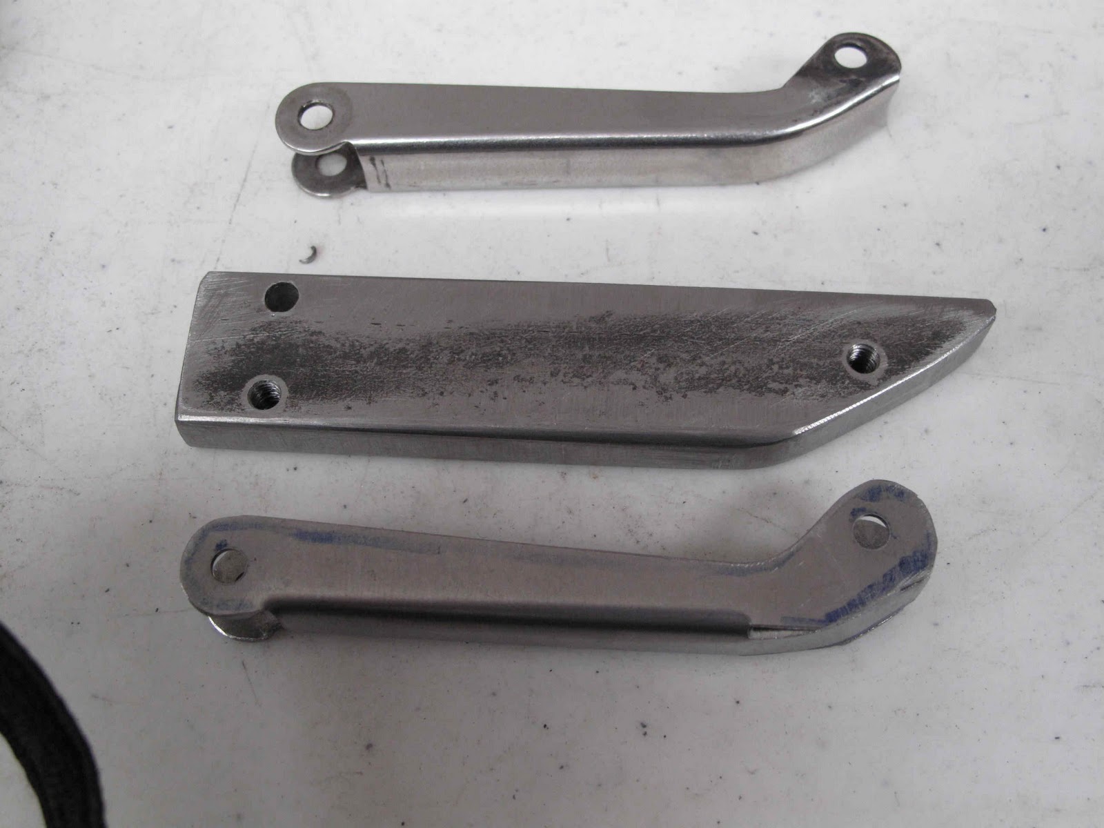
The original, the form, and the bent part ready for welding.
Before welding I made a couple more parts.
Before welding I needed the holes drilled in the second side.  I couldn't use the form block and 3/16 punch to mark the hole because the holes are threaded.  The tap hole size for 10-32 threads is a #21 drill, slightly larger than 5/32".  I took a cheap 5/32" drill and cut it off shot to get rid of most of the flutes so it would be shorter and not wander much and not wear out the threads in the block.  I didn't want the hole to open up much and allow the drill to wander or it wouldn't make an accurate center mark.
I re-sharpened the drill with my Drill Doctor.  I then bolted the part to the block, removed the bolt for the hole I was marking, and drilled just enough to make a center mark .  The hole was drilled through with the center drill as done on  the aluminum link.
My first method for holding the spacing on the welded end was to use a 6-32 screw through a piece of tubing ground to .438" long with the belt sander.  This worked fine but on the second part the screw would not come apart.
For the other 2 parts (for my homebuilt project) I just used some vice grips to hold the tube snug.  OK, so I'm a slow learner, I'll use the pliers in the future.
The finished parts came out great.  Now I need to paint thee steel parts, make the knobs and the block that mounts to the window frame.  The knobs are next while I wait for the material for the block and all the hardware to assemble everything.

Monday, November 28, 2011

Window Latch Aluminum Link

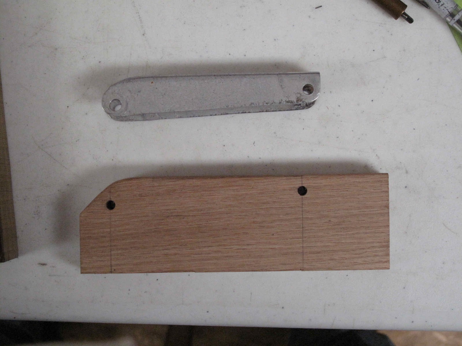
The Aluminum Link is made from .040" aluminum.  In order to form the shape needed it will be made from 5052-H32 aluminum.  To form the channel shape and the curved end I made a hardwood form block.  The first step was to locate and drill the 2 holes for the pivot pins.  The holes won't be drilled in the sides of the link until each side is bent.  The sloped end was then cut for shaping the bend in the top of the link.  A 3/32" radius was then filed on the 2 corners where the bends are formed.
Except for dead soft aluminum there is always some spring back when you make a bend.  As a result the form block needs to be tapered so the bend will spring back to 90 degrees.  The simple way to figure out how much to overbend the part is to just take a sample piece and bend it 90 degrees. The sample can be used to set the angle on the sander to taper the form block and check the finished block to make sure the angle is correct.


With the form block ready a template was made for the part.  The pivot hole will not be punched in the blanks.  It helped me to understand the part.  The small hole is for attaching the knob.  On the original part this was done with a 3/32" rivet.  I made the hole 1/8" so I could use it as an alignment hole to position the blank more easily for bending. And Locating The Pivot Holes.
A 1/8" hole was drilled in the edge of the wood form block where the rivet will later be installed in the part to attach the knob.  A hardwood backing block was made from 1/4" stock with a hole in it for a 1/8" steel rivet to serve as a dowel pin.  The hole was counter bored to allow the rivet head to be flush with the edge of the wood when everything is clamped in the vise for bending.

Don't hammer directly on the metal.  Use a wooden block to hammer on so the forces are evenly spread and the aluminum doesn't get dented.  With the relief angle on the form block the bend springs back to a nice 90 degrees.  I love it when a plan works.
Using the rivet hole to locate the part on the form block the 2 pivot holes on the first side can be center punched with a 3/16" transfer punch.  The 3/16" pivot holes can now be punched with the Whitney punch.
Two 3/16" bolts and the rivet are were used to hold the part in position for the second bend.

With both bends made the transfer punch was used again to center punch the pivot holes on the second side through the form block.  This assures the holes are positioned at the correct spacing and square so the linkage will move freely.
There is no way to get the punch into the marks for the hole on the second side so they need to be drilled.  I find regular twist drills hard to control accurately.  I also find it's easy for a twist drill to act like a reamer and open up the first hole in the thin aluminum by rubbing on the side of the drill.  The small pilot drill on a center drill along with it's smooth sides make it perfect for drilling through the first hole into the center punch on the inside.  You just have to leave enough of the drill sticking out of the chuck to drill through the second side.  I also used a thin 3/16" washer to protect the aluminum from the spinning chuck.
We now have a well formed part with all the holes properly located.  The next step is to form the end down to a nice curve.
In order to form this end down it is necessary to shrink this end of the channel.  The trick is to form the metal inward to form a wave in the middle, anneal the wave and then smash it down flat without widening out this end of the link.  This is why I chose 5052, it's easy to anneal the area needed without annealing the whole part.  First I ground off 2 washers to use to hold the metal tight to the form block while giving room to hammer the corner to the middle with the rawhide mallet.  The rippled area was then annealed by coating it with soot from the acetylene torch and warming it with a neutral flame to heat off the soot just in the rippled area.
To keep the sides from moving out the link was put back on the form block and the sides protected with fender washers.  Then the ripple was hammered down.  A harder form block would have made this work out better so I made a small steel block to just planish the area a little.


The finished part should work just fine.  The next part to make is the steel link.

Saturday, November 19, 2011

Window Latch Door Brackets (Cessna 0411595)

These brackets are the 2 aluminum brackets riveted and screwed to the inside of the door.  They are made of .040" aluminum and are badly worn.  Because they are so small and so worn, I've decided to replace them with steel parts made from .040" 4130 steel.
 These are easy parts to make by cutting out a blank bending it and punching the holes.  I would like them to line up with the existing holes and have the pivot hole square to help the latch work easily.  The first step is to make the blanks.  I prefer to make a template for every part from galvanized steel.  It allows me to work out any issues without wasting expensive aircraft materials.  If you are making more than one part it saves layout time.  Also holes can be transferred from the template to the part so they all come out within a tolerance which make them interchangeable (remember Henry Ford).
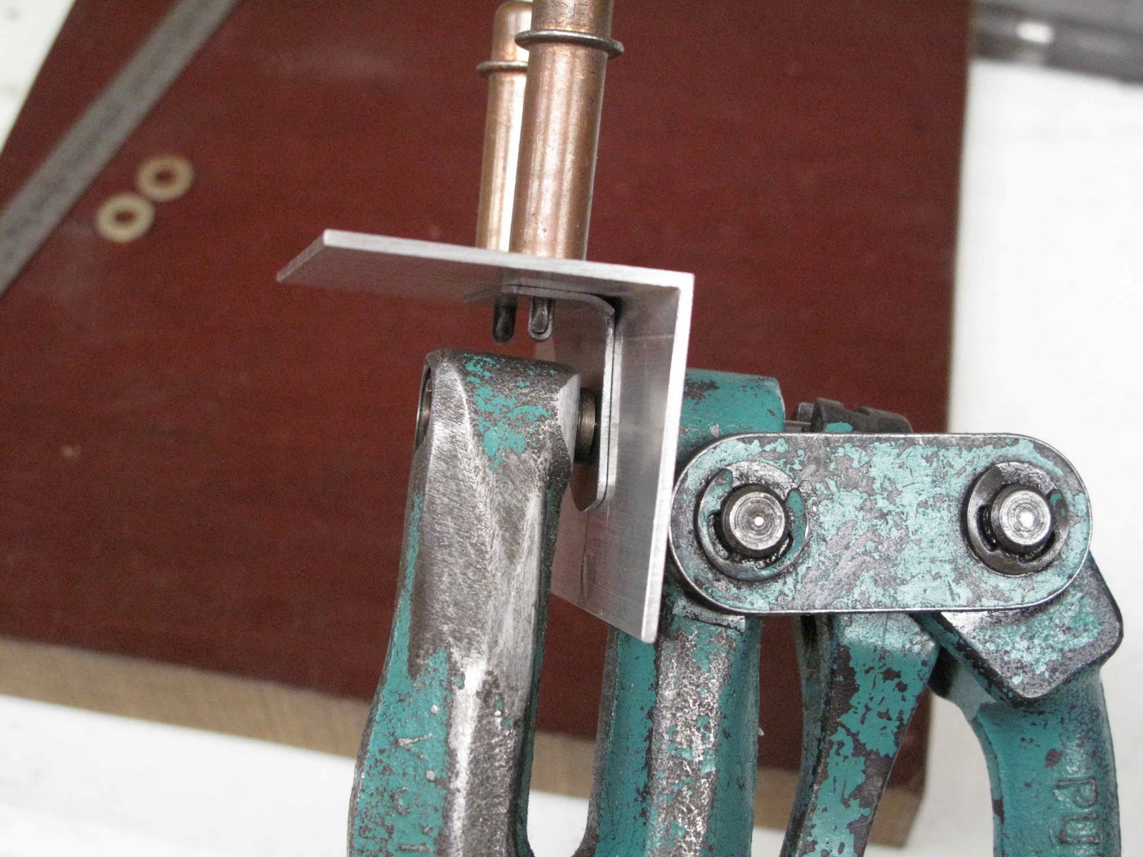
 The 2 mounting holes are 7/8" apart.  Once the template is made you can check it against the holes in the door to make sure it's right.  If you're not familiar with matched hole construction go read the articles in Sport Aviation on building the Thorp T-18 (Early 1960s).  Matched hole construction is one of the best kept secrets of sheet metal work.  Today we can accomplish this with a CNC punch press and a computer, assuming you have a couple hundred thousand dollars to spend on a press.  The rest of us just use a Whitney Punch (#5 Jr. Hand Punch) with an extra set of punches.  You need to take one set of punches and carefully grind off the centering nib.
By positioning the template on the metal for the part you then carefully slip the punch without the nib into the hole in your template squeeze and punch a hole in your part.  As I get each hole punched I insert a cleco clamp to help keep the template from shifting around.  You will note I am not adding the pivot hole at this time.  I'm good but not good enough to get them in the right spot after forming so we'll add them later.
 Once the holes are punched just draw the outline with a soft pencil or a scribe.  If you use a scribe just be careful not to scratch somewhere that will end up on the finished part.  We don't want any cracks forming on our stray scratches.  I prefer to punch all the holes I can before cutting out parts.  If I mess up punching hole I don't have to throw away my labor cutting out the part, just some metal.  I made some extra parts just-in-case my clever plan for forming them, etc. doesn't work out well and I think I'll use these latches for my next homebuilt project.
 The parts are cut out and de-burred, ready to form.
 To form the parts I cut a piece of 1/4" x 1" mild steel.  Next I transferred the hole locations to it, from the template,  using the 1/8" punch with the nib on it as a Center/Transfer punch.  In this case there was nothing to do but carefully drill the holes using these center punch marks.  I then counter drilled the back side of the form piece so I could use some 1/8" steel rivets as locater pins for bending the parts.  A 3/32" radius was ground and filed on the corner of the form block and the rivets were epoxied into the holes to make using the tool easier.
 With the epoxy dried the parts just need to be slipped over the pins and the whole thing clamped in the vise for forming.

A hardwood block works fine to bend the parts over the form block.  By using a narrow piece of steel for the form block the part can be slightly over bent to get the angle exactly 90 degrees.


Left and right parts are just a matter of reversing the part when forming the bend.

The next step is to locate the pivot hole in one of the parts.  I used a scrap of some 1-1/2" x 1/16" aluminum angle from Lowe's for this fixture.  First a line was drawn on the inside of the fixture.  The top rivet hole and the pivot hole are on the same line.  The top hole was transferred to the fixture so it was on the line and then the bottom hole, keeping the bent part clamped tightly to the side of the fixture.  The 3/16" pivot hole was punched in the fixture.  By clecoing the parts to the fixture the pivot hole can be transferred so each parts is within a tolerance that they are all interchangeable.

Then on the outside of the fixture a line was drawn through one of the mounting holes and the finished part clecoed in place.  The last part was clamped in place an the mounting hole lined up and center punched on the fixture with the 1/8" punch.  With that part clamped and clecoed to the first hole the second mounting hole can be marked and punched.

Now the part with the pivot hole and the mating part without can be clecoed to the fixture and the 3/16" pivot hole transferred to the second part.  The parts now fit the holes in the door and the pivot holes are squarely aligned so everything will move freely.  I have enough parts to do both doors, they are interchangeable and I have some spares for my next project, as well as the tools to make more.

Owner Produced Parts are really a lot of fun and easier to make than to write about.