Showing posts with label Engine. Show all posts

Wednesday, February 26, 2014

Generator and Starter Manuals

One of the things I've been trying to do with this project was to do everything according to the correct manuals, service letters, etc.  When I got ready to work on the starter and generator I realized I didn't have the manuals for them.  The starter, generator and voltage regulator were made by Delco-Remy and used on a lot of small Continental engines so I assumed the manuals were easy to find.  I went to the C-140 club library but no luck.  I then checked the forums but again no luck.  I tried all kinds of on line searches using the part numbers, etc.  I eventually found a web site for people working on old Chevy's and things went quickly after that.  
Each year Delco-Remy published a collection of Service Bulletins in an Electrical Equipment Operation and Maintenance Handbook.  This book is number DR-324.  They also published a separate collection of Service Bulletins with the Test Specifications needed to do the actual tests, repairs, and adjustments.
On January 1, 1956 they published a version of these 2 books which collected all the prior annual versions of this information into 2 books so you didn't need all the individual prior year copies.  After that they published annual updates again.  Prior to the 1956 edition the individual Bulletins were only updated as needed.  As an example I found the 11-20-49 version of DR-324 on line.  The Generator Operating Principles Bulletin 1G-100 in it is dated 1-22-46 which superseded one dated 12-28-38.
I couldn't find the test spec book on line and finally purchased a 1956 copy from a company in Israel.  It came by mail in about a week

For the Generator there are 3 bulletins.  I've shown the first pages of each here.  The three are:

1G-100 Operating Principles Generators, 7-22-46, 4 pages
1G-125 Types and Designs of Generators, 12-16-46, 6 pages
1G-150 Adjustments, Test and Maintenance of Generators, 2-4-49, 12 pages


To test the generator there are 2 Service Bulletins.

The first is 1G-180 Numerical Index - Generator Service Test Specifications, 1-1-56, 7 pages.  You use this one to look up the specific generator model number to find the applicable specializations in the second bulletin. On the C-85-12 the generator model number is 1101890.  It's near the bottom of the first column of page 2, below.  It shows that the test spec to use for this model is 1814, the generator turns clockwise, and the brush spring tension is 24 ounces.

The second Generator Test Bulletin is 1G-185 Generator Service Test Specifications, 1-1-56, 6 pages.  It gives the Field Current, Output Amps and Volts at the rated RPM. as well as other information.  Spec 1814 for this generator is on page 5, below.

For the starter (Cranking Motor) there are 4 Service Bullletins:

1M-100 Operating Principles - Cranking Motors, 7-24-46, 4 pages
1M-120 Cranking Motors Using Overrunning Clutch Drive, 8-30-46, 4 pages
1M-130 Cranking Motors Using Dyer Drive, 9-9-46, 4 Pages
1M-150 Adjustments, Test, and Maintenance of Cranking Motors, 3-2-49, 13 pages


To test the starter there are, again, 2 Service Bulletins.

The first is 1M-180 Numerical Index - Cranking Motor Service, 1-1-56, 4 pages.  Again, you use this one to look up the specific starter model number to find the applicable specializations in the second bulletin. On the C-85-12 the starter model number is 1109656.  It's near the bottom of the third column of page 4, below.  It shows that the test spec to use for this model is 2377 and the starter turns clockwise.

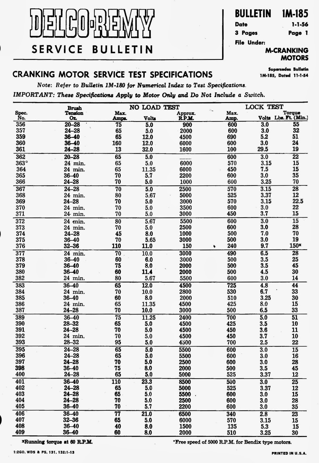
The second Cranking Motor Test Bulletin is 1M-185 Cranking Motor Service Test Specifications, 1-1-56, 3 pages.  It gives the Brush Tension, Cranking Amps, Volts, and rated RPM. as well as other information.  Spec 2377 for this starter is on page 3, below.


The Voltage Regulator used on the C-85-12 is Model N0. 118736.  The Service Bulletin for it is 1R-116 D-R 1118300 Type Two - and Three - Unit Regulators, 2-8-49, 10 pages.

The Regulator Service bulletins are:

1R-180 Numerical Index - Generator Output Control and Relay Service Test Specifications, 1-1-56, 5 pages
1R-185 Generator Output Control and Relay Service Test Specifications, 1-1-56, 10 pages.

The test spec or the 118736 Regulator is 2165 which is in Table 2 of 1R-185.

While it took several weeks to find all the Bulletins, it seems better to service the units based on the Bulletins rather than a lot of well meaning advice which may or may not be reliable.  Delco-Remy went to a lot of trouble to provide these and a lot of GM vehicles and Continental Motors were serviced using them.

Wednesday, November 6, 2013

Engine Baffle Fastener Springs

 To wind the springs I'm using a Porter Spring Winder which I borrowed from Rich Wilbur for our WACO NINE projects.  I measured the wire on a spring on the Fly Baby baffles and found it was .040" so I ordered some .041" music wire from McMaster-Carr.  After a little experimenting I decided to make springs with a 1" free length, 4 pounds of force when compressed to 5/8", 2 closed turns at each end, 10 open turns, and the ends ground flat.  I wound them using the 1/4" dia. mandrel.

The first step is to bend the end of the wire and lock it into the handle.

For the first 2 turns the Pitch Gauge is moved clear of the coil so the winds will be tight to each other.


 After winding the closed turns the Pitch Gauge is moved to use the smallest pitch. The farther you turn the handle the wider gap it forces between coils.  Ten turns are wound at this setting.

Then the Pitch Gauge is moved clear and 2 more closed turns are wound.


 The mandrel is about a foot long so more than one coil can be wound.

To make it easier to cut the springs apart I put a couple open turns, then started with 2 more closed turns, etc.

 I needed 8 springs and 4 fit well on the mandrel.

The wire was cut off as close to the closed coils as possible.
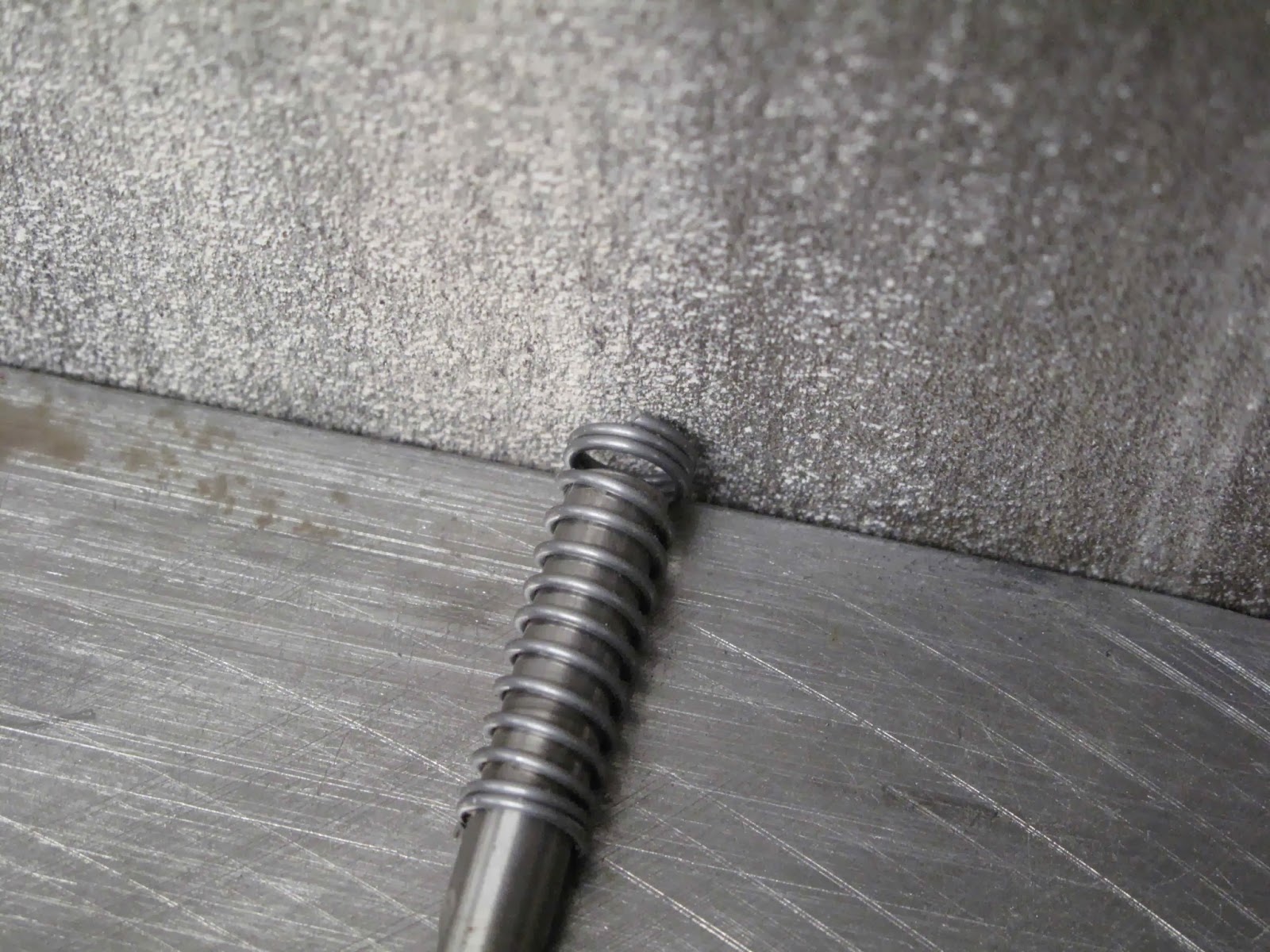
To hold the spring while grinding each of the ends I slipped it over a 19/64" drill, keeping the end of the drill clear of the belt sander.  The end was then ground square and flat on the belt sander.  I found it worked better if the cut off end of the wire were at the top where you can see it. Then you just grind with a light touch until the cut end is just blended smooth.


They make a spring force tester but I don't have one.  To check the force I set my vernier to extend the depth gauge 5/8" and locked it.  Then I just used the vernier to push the spring down until the end of the depth gauge just touched the table on the scale. It's not quite touching in this picture.  You can see we're right around 4 pounds with the spring compressed.  I figured out a way to use my magneto timer, buzz box, to determine when the vernier just touches the table.  You need an insulator between the top of the spring and the vernier.

All the wires and springs are made.  The 2 original wires are at the top, hooked together.

The original wires were very rusty so I decided to paint the springs and wires.

We now have all the fasteners ready to install the baffles.

Monday, November 4, 2013

Baffle Spring Fastener - Wires

 The baffles are attached to the studs on the engine except where they are held snug to the cylinder cooling fins.  Here the baffles are attached with wires which have a spring to hold them snug as the cylinders expand and contract do to temperature.  The springs on the Fly Baby engine baffles (C-85-8) have about 2-4 pounds of force so that's what I'll use to make springs for these.
The first task is to make the wires which have a loop at one end and a hook at the other.  There are 4 fasteners P/N 0450277-1, 0450277-2, 0450211-1 & 0450211-2.  I only have the wires, no springs, for 277-1 & -2. They are shown at the upper left,  They go through the rear baffle and loop around the cylinder.  After measuring carefully I found there is only 5/8" for the compressed springs.

Holding the other cylinder baffles in place I measured from the baffle to the hole in it's support piece.  Allowing 5/8" for the compressed spring 211-1 needs a 3" wire and 211-2 a 4 1/2" wire.  The wire for 277-1 is 2 5/8" and for 277-2 it's 11" long from the bottom of the loop to the hook.
There is a washer between the loop and the spring.  I used an AN960-8 for this.  It gives a nice surface for the spring to ride on.


 The old rusty wires measured .050" in diameter so I bought some .051" music wire from McMaster-Carr.  I thought I could carefully unwind what I needed and put the rest back in the box.  That was a fools mission.  Free the coil, tag it, and store the left overs in a Ziploc bag with a little Corrosion-X.
The first step was to straighten enough to make a wire.

 I bent the loop end around a 1/2" rod.  A 7/16" rod might have made a loop closer to the original size but this worked.

I didn't want the sides parallel because I wanted a little tension on the loop once it was done, like on a safety pin.

 The first 3 bends are just 90 degree bends done with the needle nose pliers.

 The third bend has to be positioned so it will be in the right place when the lop is closed.  It took a couple bends to figure out where to make it.  In the end I placed the pliers so they were at the top of the first leg with the sides parallel and the wire ended up just below the first leg when closed.
I bent the end over the wire to about 30 degrees, trimmed it of, and the squeezed the end tightly closed.


 The hook end has a nice radius, not a sharp corner, so I bent it around the blade on my sheet metal pliers.  I had previously filed a smooth radius on the edges of the blades.

Measuring the length from the bottom of the loop to the edge of the blade worked close enough.

 With the wire loop parallel to the blades the hook has bent by pushing the wire against the table while making the bend.


 After cutting the hook to length I cleaned it up on the belt sander.  I cut myself on enough things I didn't want any more sharp edges.  I just noticed there is a drop of blood on the table from poking myself.  That's why I were safety glasses 24-7.

On to making the springs