I was ready to put the cylinders on but my ring compressor was missing. I think I used it at my son's working on a car. I picked one up at Advance Auto only to discover it doesn't come apart. The normal assembly process is to install the piston on the connecting rod and then tighten the compressor over the rings. Then the cylinder is slid down over the piston and the compressor removed. To do that the strap has to come apart.
Fortunately the oil ring is above the piston pin so I can compress the rings and install the piston into the cylinder. Then just put the whole thing on the rod and slide in the pin.
Everything gets well oiled. Oil is worked into the rings and all surfaces are coated with oil so no bare metal parts ever rub against each other.
The piston and cylinder is ready to install.
Cylinder 1 is on.
4 Cylinders ready to torque the nuts. All the nuts are tight. I decided to snug them all down and then torque them once all were ready. You tighten them to half the torque value and then to the final torque. At this point its 8:30 in the evening and still almost 90 degrees in the attic. I'm done for today. I need to torque these when the brain is working well and I'm not in a hurry to escape the heat.
I keep the engine covered with plastic bags when I'm not working on it.
Monday, July 23, 2012
Sunday, July 22, 2012
Cylinders Ready
The cylinders are ready to install. Before installing them I decided to take the valves back out and measure all the parts and fits to find out how much life to expect out of all the parts. The cylinders were bored .015" oversize and repaired as needed with new valves, springs, pistons, piton pins and rings by Buldoc up in Minnesota. As with the rest of the engine everything was found to be at the Maximum Material Condition, i.e. long life side of the tolerance. This has probably been the best news during this whole project. The engine should be reasonably expected to achieve the 1800 hour TBO (SIL98-9A). The wooden post is the stand I made, using a piece of 4x4, to set the cylinder on while removing or installing the valve keepers. The old (1945) training video on overhauling the small Continental makes the Overhaul Manual much easier to understand. The details have changed a lot since then but the basic tasks and tools, not so much.
Saturday, July 21, 2012
Accessory Case Installed
The oil pump gears gears are in the accessory case. The gears are on the crankshaft and camshaft. The timing marks lined up with the crank and cam in the correct positions so I assume it will all work fine. The bolts on the gears are on the list (SB97-6) of mandatory replacement at overhaul.
The accessory case is on as well as the valve lifter plungers and covers. It's cool to see it going back together after all these years setting. The overhaul manual could have used a few more pictures and less words. Safetying the screen and pressure regulator cap took three tries. I should have just done it and not read the instructions. I'm trying to make sure I'm really doing things right not just how I've always done them.
Thursday, July 19, 2012
Crank Case Assembled
Everything is oiled or lubed per Continental Letter SIL99-2B. The silk thread was a little more trouble because I tried doing it with latex gloves. If you touched the sealant the cloves stick to it. Don't try this with gloves. Most of this stuff like the Moly on the tappets and cam come it small amounts which should last for about a hundred engines. The 2-4 case is setting on a plastic tote pan to allow the rods to hang freely.
The pink on the 1-3 case is the Continetal Gasket Maker.
All assembled, bolts torqued and safetied. The yellow rod protectors are pieces of those foam noodles the kids use in the lake. A short piece of it works great and fits the rod snugly. You do have to move them as you rotate the crank but otherwise they work fine.
The pink on the 1-3 case is the Continetal Gasket Maker.
All assembled, bolts torqued and safetied. The yellow rod protectors are pieces of those foam noodles the kids use in the lake. A short piece of it works great and fits the rod snugly. You do have to move them as you rotate the crank but otherwise they work fine.
Wednesday, July 18, 2012
Crankshaft Assembled
With all the parts cleaned, inspected, and repaired I had hoped to begin assembly of the engine while the grand kids were here. Unfortunately it was 100 degrees in the attic. It's still hot but in the 80's so I can work until I'm wringing wet.
The first task was to assemble the crank and connecting rods. With new bearings and hardware it's pretty straight forward but it takes a little time. Everything gets well oiled so nothing moves on dry metal when the engine starts. The rods have to be oriented so when the assembly is installed the numbers on the rods are on top. Each bolt gets torqued to the minimum limit and if the cotter pin won't go in one of the 2 hole then the torque is increased until one hole works. You can't go past the maximum torque or you have to try another nut. I actually had 2 sets of nuts just in case but all stayed below the max. When you are torquing a fastener you can not just add more torque. You need to first loosen it a little and start over so the torque is reached while moving in a slow stead motion. I prefer a breakaway torque wrench so there is a little trial and error to finally get the pins to all fit. By the last one I was pretty good at guessing how much to increase the torque to line up the hole.
Thursday, July 5, 2012
Aileron Pulley Brackets
While the grand kids were visiting for 4th of July the weather was hot and humid. We had plans to get several projects done while they were here but it was to miserable to work. We did get the aileron pulley brackets back in one morning. With one of them on the inside working a wrench and one on the outside we got them in, which I could not have done by my self. Each got a turn inside and out even laying under the plane to work the wrench.
It was good fun for me and they have more memories of helping grandpa work on his airplanes.
Sunday, July 1, 2012
Rudder Pedals and Control Column Installed
The control column went back in OK, but I should have installed the link between it and the elevator bell crank before the fuel lines. Everything works smoothly.
The rudder pedals were a pain. It all fits in nicely. The first problem I had was that there are some raised letters (part number) cast on the side of the bearing blocks. Those have to be positioned so the flange on the horizontal tubes rub on the opposite side. That makes good sense from a bearing point of view but even more sense since that extra width binds up the rudder pedals. I had one wrong and didn't notice it until I had the mounting bolts tightened. I should have noticed when I had trouble getting the bolts to go in easily. Fortunately it was on one of the outboard blocks which are easy to get the nuts installed. Some genius engineer at the factory turned the formers that the inboard block mount to so the nuts are almost impossible to install. They are a "C" section former with the opening turned toward the center console. Had they been turned outboard it would have been easy. Instead I spent 3 hours sweating to get 4 nuts installed and tightend. What A Pain!
See the screws behind the rudder pedals. They're for the cabin heat control and they're what the parts manual shows. Unfortunately 3 of the catch on the rudder pedal when it's full forward. They may never move that far with the cables hooked up but it's not worth the risk. I've turned the around but I plan to replace them with rivets. The heat control was riveted on when I got the plane. I don't know if it was done at the factory and they never corrected the parts manual or what. I found nothing about it at the 120/140 web site or in a service letter.
The next problem I had was the cover below the pedals. Brakes on the passenger side were an option which could be added in the field. Part of that was cutting out this cover to clear the added linkages. I don't know if it was done poorly or the pattern was wrong, but the openings were not cut far enough aft. This caused the linkage to hit the cover and bend it far enough to start it cracking. I trimmed the opening about an inch farther aft so it just clears.
The cover on the left side is a right pain to get in around all the parking break cables and linkages. Once it was in I realized I put the clevis pins, at the bottom of the pedal link, in backwards. They should be installed outboard to inboard. The end of the pin on the left pedal snagged the cover as the brakes were operated. All the pins are now pointing inboard. The cover was still close so I trimmed it about 1/8" to get good clearance. Having anything snag even a little would be to exciting while landing.
There is one more cover which protects the pulleys next to the rudder pedal. Unfortunately that is missing so I'll have to make one after I get all the cables back in.
If you look close at the pedal tubes you'll see black paint is scratched through to the primer. I was impressed with how nice the epoxy paint was to work with but I'm back to using good old engine enamel. The paint on the engine parts is so much harder to scratch. The engine cylinders did get baked a little which you can't do with epoxy. They sat out in the sun for about 6 hours. By the end you could not smell the solvents anymore. I was curious how hot they would get as the outside temperature rose to 97 deg. I have an infrared thermometer so I kept checking the temperature of the paint all day. This picture was at about 10 AM and the outside air was 85 deg. and the parts were at 125 degrees F. They never got any hotter as the day warmed up. All the heat is coming from the sun not the air. The finished paint is way tougher than the epoxy.
Tuesday, May 15, 2012
Stationary Instrument Panel - P/N 0412491
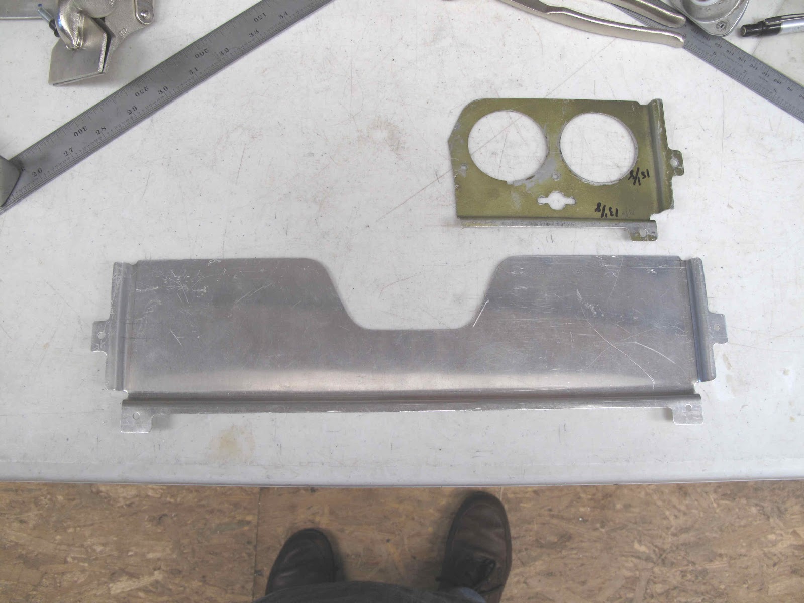
The primary instruments are on the oval shock mounted panel (1). The ammeter, clock, oil pressure and oil temperature are on a stationary (not shock mounted) panel (20). This panel is screwed to the back of the large panel (72) which is riveted into the fuselage structure. This makes a simple mount for the gauges and makes a nice box for lighting the gauges. Unfortunately someone cut off most of the panel, for reasons I wouldn't even attempt to guess. At least there was enough to figure out how it was made.The panel is made from .032" 2024-T3 aluminum. The notch in the middle provides clearance for the center instrument on the main panel. I made the blank long on each of the folded sides so I could cut everything to fit after making the bends. The first bend was an easy 90 degree bend along the bottom.
I don't have a break to form the second bend so I used a piece oak the thickness (3/8") of the step in the bends, all clamped down to a board under the panel. I routed a 1/8" radius on the edge where the bend was formed. The piece of 1x2 behind the bend is there to keep the bends square. The piece of oak needed a 5-7 degree taper to allow for spring back in the bend. Since the bend gets trimmed so close it was easier to just bend the ends with the tabs to an exact 90 degrees after trimming.
A block of wood with the relief angle on it worked great for for the first bend on the ends.
The same piece of oak was used for the end bends. One thing you can see in this picture which wasn't in the long bend is the clamps used to hold the backing block tight while making the bend to get a nice tight bend .
The flanges are all bent, ready to trim
The radii in the corners of the tabs were punched and the tabs cut to size. The long cuts were made with the band saw.
The next step was to locate the instrument holes. I'm tall and with the instruments in the original locations the top of the instruments are blocked by the front panel. With a little work I figured out I needed to move the gauges down 1/8" so I can see the whole dial in the panel opening. The colored marks were how I worked out the offset.
The panel needs the holes for the lights and some paint to help reflect the light. I have an idea about the paint color, etc. I'll cover it later.
Sunday, May 13, 2012
Assist Handle - P/N 0413106
Someone removed the Pilot side handle (passenger side shown) to make room for a large instrument at the end of the shock mounted panel. The 2 end instruments were originally 2 1/4" size and only used as options. The handle was stamped from .040" aluminum.
My first effort was to just hammer out one. I made a form block which includes the curve of the instrument panel. The idea was to anneal the aluminum, draw it part way, then re-anneal it and repeat as needed. It would probably work if I could anneal the aluminum better. They make markers to use to control the temperature. I did it with the simple method of coating the aluminum with soot and then heating until the soot disappears. It worked pretty good but I don't think I got it evenly heated. It probably works better with a bigger torch.
You can see it was forming fine but it always ripped open on the second pass. Clearly I need to learn more about this process.
I decided instead to make the part from 3 pieces and gas weld them together. The center part I formed using some blocks of 1x2 and clamps for a break. I also left it a little short on depth so I could stretch it a little after welding to work harden it.
I made the center part the full length so I could cut it down to fit the end pieces.
Before I made the end pieces I decide to stop and learn to gas weld aluminum. I have a few books on the subject and some videos. How hard can this be? I recently took a refresher course on gas welding steel but the instructor knew nothing about gas welding aluminum. He was into TIG welding aluminum. I have no money for a TIG welder. For things like this I can work easily on the little deck outside my attic shop. Unlike 4130 steel a slight breeze isn't a big deal. The bucket has warm water for scrubbing off the flux which is very corrosive.
My first tries were pretty bad. To much heat, moving to slowly, very erratic and lots of holes. Nothing I read or watched really showed the weld puddle up close. You need good light so you can see the texture of the surface as it just darkens slightly and gets rough looking almost like a cold solder joint. As soon as that starts to happen the edges of the metal start to swell up slightly and separate. That's when the rod, which is being held just at the edge of the flame so it's hot but can't melt, gets pushed into this start of a puddle. Pull out the rod, back off the flame and you have a tack weld. Of course that assumes you cleaned the parts,clamped them so they are tight together and fluxed just along the seam as well as the rod.
On this thin (.040") aluminum you need tacks every 1/2" - 3/4". As you weld you need to back out the flame about every 1/2" to keep from over heating the joint. It's actually just like soldering on copper foiled stained glass work. You have to get everything hot enough for the solder to flow onto and between the copper foiled edges of the glass. Get it just a little to hot and the solder runs out the bottom. I'm sure with practice you can get so you just keep welding the full length of the seam by moving the heat in and out as you go. Once my welds got this good I was sure I could do this well enough to make my part. I had welded about 10' - 12' of seams at this point. I'm not ready to weld a gas tank but I know I can do it with more practice.
To make the end pieces I first annealed a piece of aluminum and folded it with about a 1/2" radius so it would fit in the form block.
To hold it down while forming the piece I clamped a file handle into the form block. I pounded it in with a hammer to give the bottom the curved shape I wanted, then I clamped it down. This prevented the metal in the bottom from being stretched to much.
By hammering the flat part down starting at the outer edges, with a rawhide mallet, you get a nicely wrinkled part. The wrinkles on this one are perfect. After annealing you just start at the outer edge of the outside wrinkle and start working inward flattening it. This shrinks the metal making it thicker while flattening it.
I don't need it perfectly flat at this point. Once its welded it will be nicely annealed around the weld. I can anneal the flat areas and finish flattening them. The 2 end pieces were band sawed and smoothed with the belt sander to give a very straight edge. They are not parallel. I'll trim the center piece to fit these. Also the seam is between rivet holes so no rivet goes through a seam.
The first end is welded to the center. I welded on the bottom side because it was easier the welding onside the handle.
Now the welded assembly was trimmed to fit the other end piece.
All 3 pieces are now welded and well cleaned to get rid of the flux.
The welded assembly goes back into the form block to have the handle form finished. It also hardened the metal. The flat areas at the ends were also hammered flat on a thick piece of aluminum to smooth them and harden them.
The top 3 side of the handle go under the skin around the handle. The bottom flange goes on top of the panel edge that the skin is attached to so it needs to set higher. By clamping a strip of aluminum under that flange the rest of the part is hammered down to create the offset.
With a little trimming and punching the rivet holes the part is done. I'm going to paint it before I install it since it is not made of a corrosion resistant aluminum. It fits perfect and once installed you'll be hard pressed to even notice it's not original. I've got several more aluminum welding projects ending with a new gas tank for the Fly Baby.
My first effort was to just hammer out one. I made a form block which includes the curve of the instrument panel. The idea was to anneal the aluminum, draw it part way, then re-anneal it and repeat as needed. It would probably work if I could anneal the aluminum better. They make markers to use to control the temperature. I did it with the simple method of coating the aluminum with soot and then heating until the soot disappears. It worked pretty good but I don't think I got it evenly heated. It probably works better with a bigger torch.
You can see it was forming fine but it always ripped open on the second pass. Clearly I need to learn more about this process.
I decided instead to make the part from 3 pieces and gas weld them together. The center part I formed using some blocks of 1x2 and clamps for a break. I also left it a little short on depth so I could stretch it a little after welding to work harden it.
I made the center part the full length so I could cut it down to fit the end pieces.
Before I made the end pieces I decide to stop and learn to gas weld aluminum. I have a few books on the subject and some videos. How hard can this be? I recently took a refresher course on gas welding steel but the instructor knew nothing about gas welding aluminum. He was into TIG welding aluminum. I have no money for a TIG welder. For things like this I can work easily on the little deck outside my attic shop. Unlike 4130 steel a slight breeze isn't a big deal. The bucket has warm water for scrubbing off the flux which is very corrosive.
My first tries were pretty bad. To much heat, moving to slowly, very erratic and lots of holes. Nothing I read or watched really showed the weld puddle up close. You need good light so you can see the texture of the surface as it just darkens slightly and gets rough looking almost like a cold solder joint. As soon as that starts to happen the edges of the metal start to swell up slightly and separate. That's when the rod, which is being held just at the edge of the flame so it's hot but can't melt, gets pushed into this start of a puddle. Pull out the rod, back off the flame and you have a tack weld. Of course that assumes you cleaned the parts,clamped them so they are tight together and fluxed just along the seam as well as the rod.
On this thin (.040") aluminum you need tacks every 1/2" - 3/4". As you weld you need to back out the flame about every 1/2" to keep from over heating the joint. It's actually just like soldering on copper foiled stained glass work. You have to get everything hot enough for the solder to flow onto and between the copper foiled edges of the glass. Get it just a little to hot and the solder runs out the bottom. I'm sure with practice you can get so you just keep welding the full length of the seam by moving the heat in and out as you go. Once my welds got this good I was sure I could do this well enough to make my part. I had welded about 10' - 12' of seams at this point. I'm not ready to weld a gas tank but I know I can do it with more practice.
To make the end pieces I first annealed a piece of aluminum and folded it with about a 1/2" radius so it would fit in the form block.
To hold it down while forming the piece I clamped a file handle into the form block. I pounded it in with a hammer to give the bottom the curved shape I wanted, then I clamped it down. This prevented the metal in the bottom from being stretched to much.
By hammering the flat part down starting at the outer edges, with a rawhide mallet, you get a nicely wrinkled part. The wrinkles on this one are perfect. After annealing you just start at the outer edge of the outside wrinkle and start working inward flattening it. This shrinks the metal making it thicker while flattening it.
I don't need it perfectly flat at this point. Once its welded it will be nicely annealed around the weld. I can anneal the flat areas and finish flattening them. The 2 end pieces were band sawed and smoothed with the belt sander to give a very straight edge. They are not parallel. I'll trim the center piece to fit these. Also the seam is between rivet holes so no rivet goes through a seam.
The first end is welded to the center. I welded on the bottom side because it was easier the welding onside the handle.
Now the welded assembly was trimmed to fit the other end piece.
All 3 pieces are now welded and well cleaned to get rid of the flux.
The welded assembly goes back into the form block to have the handle form finished. It also hardened the metal. The flat areas at the ends were also hammered flat on a thick piece of aluminum to smooth them and harden them.
The top 3 side of the handle go under the skin around the handle. The bottom flange goes on top of the panel edge that the skin is attached to so it needs to set higher. By clamping a strip of aluminum under that flange the rest of the part is hammered down to create the offset.
With a little trimming and punching the rivet holes the part is done. I'm going to paint it before I install it since it is not made of a corrosion resistant aluminum. It fits perfect and once installed you'll be hard pressed to even notice it's not original. I've got several more aluminum welding projects ending with a new gas tank for the Fly Baby.
Subscribe to:
Posts (Atom)