Sunday, March 4, 2012

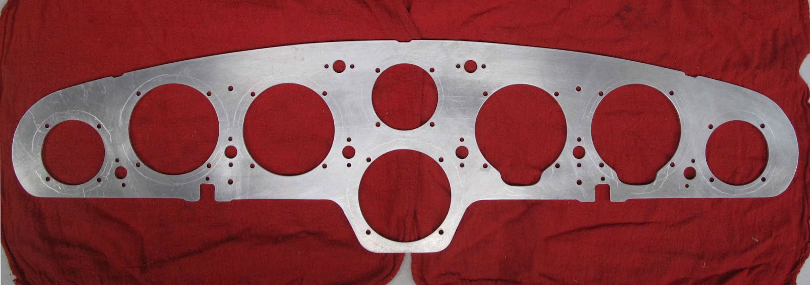
Instrument Panel 0412484 Finished

 I don't have an instrument hole punch and couldn't find one to borrow so I used the jig saw to cut out the holes.  It was slow but cheap.  To make a slot for inserting the blade to start the cut I just punched 1/8" holes 3/32" apart.  It's very easy to do with the Whitney punch but hard to do with a drill.  The drill but wants to wander into the adjacent hole.
 With the holes sawed out, the next thing was to smooth and more perfectly round the holes.  The drum sander on the Shopsmith works great for this.  I have a 2" drum which is head with the drill check for the 2-1/4" holes.
With all the edges de-burred it's ready for primer and paint.  When the paints dry the instruments and lights can be mounted.  I have to repair the original cover but it should be usable.  I like it.

Saturday, March 3, 2012

Instrument Panel 0412484

 The instrument panel is made of 1/8" aluminum and shock mounted to the frame.  I had the remains of 2 original panes, neither of which was worth using or repairing.  The easy solution was to just make a new one.  I have no interest in instrument flying so I chose to go back to just basic instruments in the original arrangement.  With the parts manual and the owners manual it was easy to figure out which holes in these parts were original and what had been added or modified.
Before I drew the new panel on the aluminum I made a CAD drawing to work out the dimensions without wasting expensive aluminum.
 This is the original arrangement of the instruments.

 Some measurements were needed to create this drawing.  Small hole sizes are easy to measure with a set of drills to use  The larger holes are measured and located by scanning the parts and bringing the scan into the CAD file. Scale the image based on the length and width which are easy to measure and just draw over the image.  Knowing things were done to fractions of an inch makes resolving exact measurements easy.
The outline is cut and the small holes punched or drilled.  The biggest holes I could punch in .125" 2024-T3 were 5/32" diameter.  Even those were hard.  The holes for the lights were punched 1/8" and drilled to 7/16" with a #5 center drill.  There are some 9/64" and 11/64" holes.  I just punched them one size smaller and used the drill press to finish drill them to size.
Now I just need to cut the instrument holes.  I don't have a cutter for this so I'll just have to use the jig saw on the Shopsmith

Wednesday, February 29, 2012

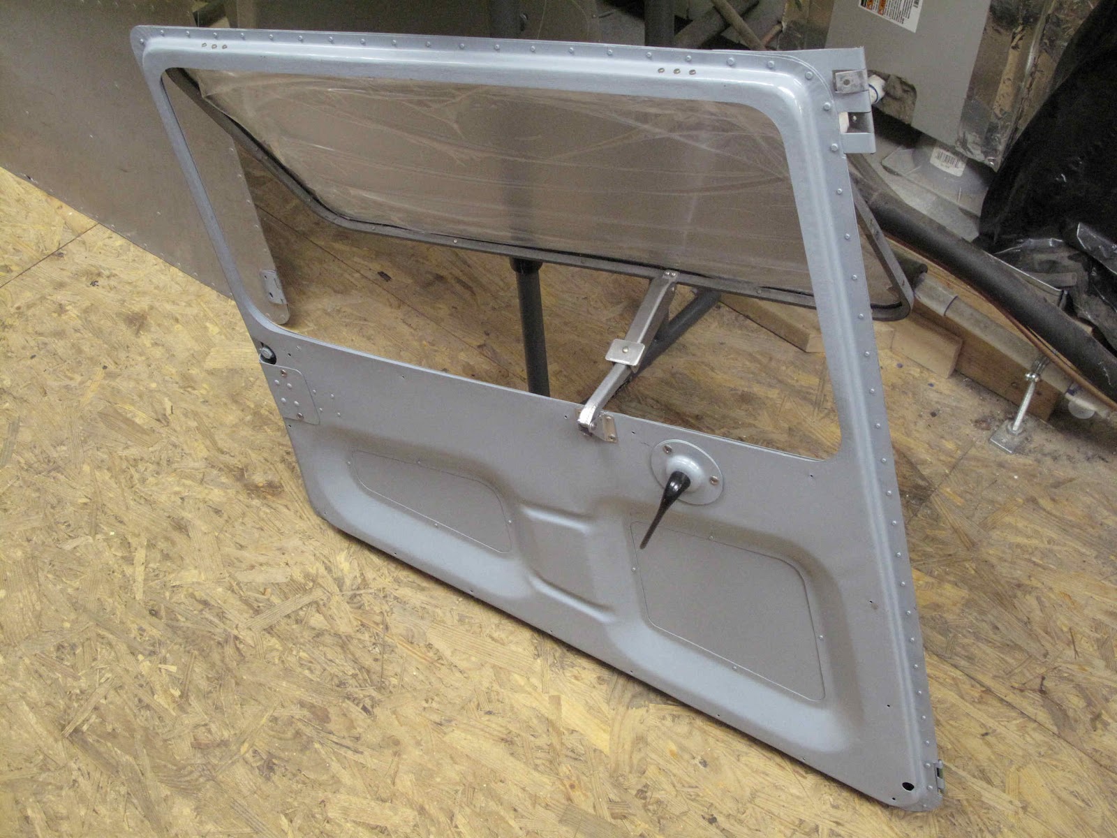
Door Window Hinges

 I found the hinges for the Pilot side door window were unusable.  The material for these is MS20257P2 which is aluminum piano hinge1-1/16" wide and .040" thick.  The easiest thing for these was to just make a little jig to hold the hinge while punching the rivet holes.  I used a piece of 1/16" x 1-1/4" aluminum angle, 2" long.  Each hinge is 2" long.The factory used a flat punch about 1/8" wide to lock the pin in one side of the hinge.  I used 2 center punches done with the 5/32" punch from my Whitney punch.  I also hammered the back end of the hinge, like on the flap hinges, to help assure the pin won't slide out.
 The hole fixture is simple.  The 1/8" holes are 5/8" from the corner and 1/2" apart.  There are 3 holes on the door side of the hinge and 4 on the window side.  It's just a matter of positioning the hinge in the corner and punching the holes through the hinge with a punch with the center nib removed, using the clecos to hold the hinge in place as the holes are punched.

 With the hinges and latch installed the window works great.  I was so pleased I decided to replace the old hinges I had installed on the passenger door with new ones also.  Good plan but as I started riveting on the first hinge I damaged the window so I had to remove the glass and start over making a new window.  Oh Well, At least it's all fun no matter how many times you do it.

Saturday, February 25, 2012

Installing Side Glass In Door Frames

 With the roto-tiller done I'm back to the planes.  The door glass is supposed to be .060" thick.  Someone had installed .125" plexi-glass which seems fine but you have to leave out the seal.  Their solution was lots of RTV instead of the electrical tape I discussed earlier.  I'm using the Scotch 2228 Moisture Sealing Tape from Lowes.  Before removing the old glass I drew the cut line on the new plexi-glass so it's 3/32" in from the inside of the stamped part of the frame.
A 1-3/4" radius worked well for the corners.  The top and rear of the frame are straight and square so there are 2 easy sides.  The other edges and the corners I cut with the slow metal cutting bandsaw.  It cut much better than the coarser toothed and faster wood bandsaw.  The edges were finished to the line with the belt sander and a little file work.
To get the piece to fit through the bandsaw I had to cut a piece from the sheet.  I have this nice straight edge with a rubber grip surface, so it won't slide around.  I just used a cheap plastic cutting knife from Lowes to score the plastic and break it.  It work great for doing the same thing on thin sheet aluminum rather than using snips.
The 2228 tape is one inch wide.  By using the straight edge and a sharp knife, with the small breakaway blades, I was able to cut the 4' strip of tape into 2 1/2" wide pieces.  Oh yeah, I have a piece of 1/4" thick glass I bought at the local window place to use for cutting such things on it.  Don't press to hard and you won't scratch it and the tape doesn't stick.  It has a release paper on one side so I cut it with the paper side up.  This stuff will stick to it's self at the slightest touch and never come apart again so be careful.  The tape was stuck to the edge of the window with the sticky, paper side, to the window and wrapped about 3/16" onto both sides.
The window was fit into the frame and everything clecoed together.  The frames were originally assembled with 3/32" flush rivets with the factor head to the outside.  The countersink is very small and appears to have been done on the inside as well.  If you drill out one of these holes to fit a 1/8" rivet you make the countersink almost disappear. Only the top half of this window still had 3/32" rivets.  The rest, on the 2 doors, had been replaced with a variety of 1/8" flat head and universal head A and AD rivets as well as some Pop Rivets.  The rivets need to be flush to clear the door frame nicely when opening and closing so I re-drilled the countersinks to fit the 1/8" rivets.
Because the seal needs to be compressed just slightly to get some of the rivets to line up well there were places where a couple clamps with some duct tape on the faces worked great to hold everything tight while squeezing the rivets.  This is one of those places where a squeeze is the only way to set the rivets.
Click on this picture to zoom in and you can see the difference in the correct and incorrect rivets.

Roto-Tiller Delays Project

 I haven't been getting much done on my airplane projects for the past couple months because I've been busy rebuilding my wife's roto-tiller.  It's a nice heavy duty 8 HP machine built about 1978.  She got it for free and I've been promising for a couple years to rebuild it.  Between the rust and dried grease nothing moved except the engine which turned over with rather weak compression.  The wheels were rusted onto the shafts and had to be cut off and welded back together in order to get the transmission apart.  Other than the tines, tires, hardware, a couple chains and the gas tank which all had to be replace, the rest of the parts just needed cleaning and painting.  A little Marvel Mystery Oil got the rings loose, and with a rebuild on the carburetor the engine runs great.

 The good news is the tiller works great.  I still need to print a couple vinyl labels I couldn't save and make a cover for the pulleys.  The bad news is I spent $900.  Fortunately You can't buy a new one this nice for that price and it was a lot of fun.

Time to plant the garden or we won't have any peas this year.


Sunday, February 12, 2012

EAA Gas Welding Workshop

I've spent this weekend in Virginia Beach practicing welding at the EAA SportAir Workshop.  It was good fun and I learned plenty even though I had to learn to weld to get my A & P back in the 70s.  I don't weld often so I've been practicing on lots of scrap and some tubing from Lowes.  I had lots of questions which I couldn't find answers to on line, in books, or in the EAA welding video.  It really was money and time well spent and good fun.  Now I'm ready to weld up the splices on my bent wing strut.

Saturday, December 24, 2011

Latches Finished

 The latches are finished and work great.  I painted the steel parts an aluminum color over epoxy primer.  Originally I worried about using clevis pins for the 2 pivots.  By carefully folding the ends of the cotter pins tight to the clevis pins I don't think you could snag yourself very easily.  I'm eager to finish the doors now.

Friday, December 23, 2011

The Fun is in the Doin'

If you've read my postings for a while you've probably noticed I'm not very orderly in working through the project from start to finish.   I tend to work on what ever I have parts, materials, tools ,or ideas for at the time.   When I helped my dad build the Fly Baby back in the 60s we were very methodical.  Pete Bowers wrote the plans/manual as a set of step by step instructions.  You start on page one of a chapter and just check off each task as you go.  When every item is checked off you have an airplane, actually a very cool airplane.

As much fun as it was working with my dad on the magic of building that plane you would think I would be more orderly in my current projects.  I'm not because what I learned from that process was that each little item was a project in and of it's self.  Each had it's own knowledge required, it's own materials, tools and methods.  To some extent it didn't matter so much the order things were done as it did that each was done.

By focusing on each small task, enjoying it, and taking pride and satisfaction in it's completion building an airplane is very easy, a lot of fun, and rewarding.  Finishing and flying the airplane was great but just one more little task or adventure just as each flight in it has been since.

By enjoying each saw cut, each hole drilled, each tool made, each little assembly, each flight for all the joy it contains, the Fun really is in the Doin' Not Just in Being Done.

Merry Christmas and a Fun New Year!

Tuesday, December 20, 2011

Window Latch Pivot Pin (Cessna 0413148)

The trick to this latch mechanism is that it folds up like a jack knife when the window is closed.  To do that, the steel link folds inside the aluminum link.  It sounds simple but the pivot at the door end of the link, which moves in and out of the aluminum link, includes the brackets and the pin holding them all together.  The parts manual calls this pin a rivet. It needs to be something with very thin heads on the ends.  The inside of the aluminum link is 3/4" (0.750") and the inside of the steel link is 7/16" (0.438").  The brackets are each 0.040" thick and the link is made of 0.050" thick steel.  Allowing a little (0.010") for clearance for the brackets and link to move, and about the same for the links to move in and out doesn't leave much to form the heads on this rivet. (.750-.438-(.050x2)-(.040x2)-.010-.010)/2=.056" for the rivet head height.  They can call it a rivet all they want I have no way to form a head on a 3/16" rivet and still have all these parts move.  As an alternative I looked at using an aluminum book binder screw (male and female parts which screw together).  They are readily available but the shaft diameter is more like 7/32" than 3/16" and the aluminum seemed very soft and would wear out to quickly.  I decided to make the same type connector with a piece of 3/16" x .035" 4130 steel tubing and an AN526C-632R6 in each end.  The screws will be held secure with Loctite.  The 6-32 version of the AN526C screw has a head height of  0.860" so it will need to be ground down to clear when folding.  After grinding there is still enough of the Phillips slots left to easily install and remove the screws.  The 6-32 screw is perfect since the inside diameter of the tubing is almost exactly the correct hole size for tapping the threads.  The head on these screws are a large enough diameter that they will hold the parts securely even as the holes in the brackets wear out larger.  Because of their size they can also be tapered nicely to more easily slide into the link during folding.
The process for making these parts is easy, thread a piece of tubing about 5/8" long and modify 2 screws.  I have no easy way to hold this small piece of tubing while threading it.  A collet would work nice but I don't have one.  I chose to use my metal bending pliers with a piece of Scotchbrite to get a good grip without scratching or distorting the tubing, it worked well.  Threading works best with some cutting oil.  After the first couple threads are cut, small moves turning the tap in a little and back a little with very light force will prevent breaking the tap.  They are very brittle.  Because of the small size and fine threads I only went about 3/6" in and then removed the tap and washed off the chips in MEK, and then re-oiled the tap.  This made it a little slow but the threads came out nice.
The piece was then cut off on the band saw and the end ground square with the belt sander.  The trick to getting a nice clean square end is to roll the tube holding it against the miter fence as you move the fence across the face of the belt.  By using a light pressure against the belt you can take off as little as .0005" in a pass.  I ground the end down to make the length about .005" longer than the desired finished length.  I counter bored the ends of the tube and this extra length left some metal for cleaning up the ends after drilling.
The counter bore is done for 2 reasons. First it assures the screws will seat completely when tightened.  The other reason is because the tap is not long enough to cut threads all the way to the end of piece of tubing.  The first few threads on the tap are not full treads to make it easy starting the tap.  The other end of the tap has a bit of a shoulder which limits the depth the tap can go.  The counter bore allowed the tap to be run in just deep enough to run the tap in from both ends to clean up the threads at the far end.
The counter bore was only done about .020"-.030" deep so there would be as many good threads as possible.
Now the tap is just enough deeper.
The 3/8" long screws had to be shortened slightly so they would both bottom out against the tube ends.  I probably could have used 1/4" screws but I used what I had.  The heads were ground down by chucking the tube in the drill and spinning the screw while grinding it.  You have to work on the side of the head which holds the screw tight or exciting things happen as the screw comes out at high speed.  That's probably why I wear safety glasses at all times, not just when doing something dangerous.
After grinding I finished the screw heads with a fine mill file to smooth them up a little more.  I don't want them to wear a notch in the sides of the aluminum link.
Except for painting the steel parts I've run out of things to do on this.  Now I can install them and put the new glass in the doors.  I didn't want to install the side glass until I was sure all this would fit and work correctly.

Friday, December 16, 2011

Aluminum Window Latch Bracket (Cessna 0411360)

 This part was originally made from an extrusion, cut to 5/8" wide and the holes added.  I don't have any way to get the extrusion or to cut the shape from bar stock with a milling machine.  Instead the plan is to use the hole saw to cut the concave curve at the rivet end and the belt sander to shape the rest of the pivot end.  I decided to make 4 pieces to make it easier.  The first step was to band saw 2 blocks 1-5/16" long from a bar of 1/2" x 1-1/4" 2024-T3 aluminum and square them up with the belt sander.
 I'm going to clamp the 2 blocks together and use the hole saw to cut down the split between them 1/4" from the edge.  Since the 3/4" hole saw will cut past the edge I need a pilot hole to assure it goes straight through the blocks.  The easy way to assure the hole is straight and square is to cut it with the table saw with half the width into each block.  The fence is set to center the cut 1/4" from the edge and the blade is set 1/16" deep.
 The 2 blocks are clamped together with the bottom and side faces lined up.  The square cut hole is drilled out to 7/32" diameter.  The drill on the cutter is 1/4" so this will leave a little for the drill to assure it fits tight as the cutter saws down through the block.  The teeth on the saw have set, so the body of the saw won't help pilot it through the hole.

 The cut is started with the block setting on the metal table to assure it is as square as possible.  Half way down a piece of smooth plywood is set under it to allow the drill and cutter to clear the end of the block.  The adjustable wrench is there as a stop to prevent the block spinning, which would be a major disaster.  This all worked perfect and turned out to be quicker than I dreamed possible.  The gap helped clear the chips.

 The points at the open end need to be removed to leave a flat area for the rivets which is also parallel to the bottom surface. Back to the table saw.  I should have made a holding block for this cut.  It didn't look this unsafe when I did it.  The blade is 1/8" from the fence and 1/4" deep.  it worked great.


 The blocks were then band sawed in half and and squared up with the belt sander.
 A piece of 1/16" aluminum angle was cut off to use as a jig for locating the rivet holes and the pivot hole.  By clamping the block against the side, and with the end lined up with the edge both rivet holes can be center punched with the 1/8" punch.


 The center punched holes are then punched with the 1/8" Whitney punch.
 By clecoing the part back in the fixture, the center of the pivot hole can be punched with the 3/16" punch.  Because this hole will be drilled I center punched the mark to improve the drill centering.  We tend to call a spring loaded punch a center punch but they really are prick punches.  The center punch has an included angle the same as a drill.  The prick punch is a much sharper angle so it will make a more accurate mark. Because the center punch angle is the same as the drill it will keep the drill from wandering better than a prick punch.


 Another help to an accurate hole is to use the center drill until the hole edge is about 1/16" deep.  Then the standard twist drill can be used to drill through withe a good hole.  Once the part is finished this hole will be drill out from 3/16" to 13/64" to give the pin some clearance to pivot easily.


To finish the shape the same method of pivoting on a bolt is used as in making the false rib tool for the Waco Nine project.  The parts are all done. Clevis pins will be used for the outboard and center pivots.  The inboard pivot was a rivet.  The clevis pin won't fit so I still need to solve that and paint the steel parts.  It all the parts fit and work as planned.  I could have bought these assemblies from Univair for $286 each.  Clearly this was more fun and may have even been cheaper even allowing for my labor because I Built 4 latches.