Wednesday, February 26, 2014

Generator and Starter Manuals

One of the things I've been trying to do with this project was to do everything according to the correct manuals, service letters, etc.  When I got ready to work on the starter and generator I realized I didn't have the manuals for them.  The starter, generator and voltage regulator were made by Delco-Remy and used on a lot of small Continental engines so I assumed the manuals were easy to find.  I went to the C-140 club library but no luck.  I then checked the forums but again no luck.  I tried all kinds of on line searches using the part numbers, etc.  I eventually found a web site for people working on old Chevy's and things went quickly after that.  
Each year Delco-Remy published a collection of Service Bulletins in an Electrical Equipment Operation and Maintenance Handbook.  This book is number DR-324.  They also published a separate collection of Service Bulletins with the Test Specifications needed to do the actual tests, repairs, and adjustments.
On January 1, 1956 they published a version of these 2 books which collected all the prior annual versions of this information into 2 books so you didn't need all the individual prior year copies.  After that they published annual updates again.  Prior to the 1956 edition the individual Bulletins were only updated as needed.  As an example I found the 11-20-49 version of DR-324 on line.  The Generator Operating Principles Bulletin 1G-100 in it is dated 1-22-46 which superseded one dated 12-28-38.
I couldn't find the test spec book on line and finally purchased a 1956 copy from a company in Israel.  It came by mail in about a week

For the Generator there are 3 bulletins.  I've shown the first pages of each here.  The three are:

1G-100 Operating Principles Generators, 7-22-46, 4 pages
1G-125 Types and Designs of Generators, 12-16-46, 6 pages
1G-150 Adjustments, Test and Maintenance of Generators, 2-4-49, 12 pages


To test the generator there are 2 Service Bulletins.

The first is 1G-180 Numerical Index - Generator Service Test Specifications, 1-1-56, 7 pages.  You use this one to look up the specific generator model number to find the applicable specializations in the second bulletin. On the C-85-12 the generator model number is 1101890.  It's near the bottom of the first column of page 2, below.  It shows that the test spec to use for this model is 1814, the generator turns clockwise, and the brush spring tension is 24 ounces.

The second Generator Test Bulletin is 1G-185 Generator Service Test Specifications, 1-1-56, 6 pages.  It gives the Field Current, Output Amps and Volts at the rated RPM. as well as other information.  Spec 1814 for this generator is on page 5, below.

For the starter (Cranking Motor) there are 4 Service Bullletins:

1M-100 Operating Principles - Cranking Motors, 7-24-46, 4 pages
1M-120 Cranking Motors Using Overrunning Clutch Drive, 8-30-46, 4 pages
1M-130 Cranking Motors Using Dyer Drive, 9-9-46, 4 Pages
1M-150 Adjustments, Test, and Maintenance of Cranking Motors, 3-2-49, 13 pages


To test the starter there are, again, 2 Service Bulletins.

The first is 1M-180 Numerical Index - Cranking Motor Service, 1-1-56, 4 pages.  Again, you use this one to look up the specific starter model number to find the applicable specializations in the second bulletin. On the C-85-12 the starter model number is 1109656.  It's near the bottom of the third column of page 4, below.  It shows that the test spec to use for this model is 2377 and the starter turns clockwise.

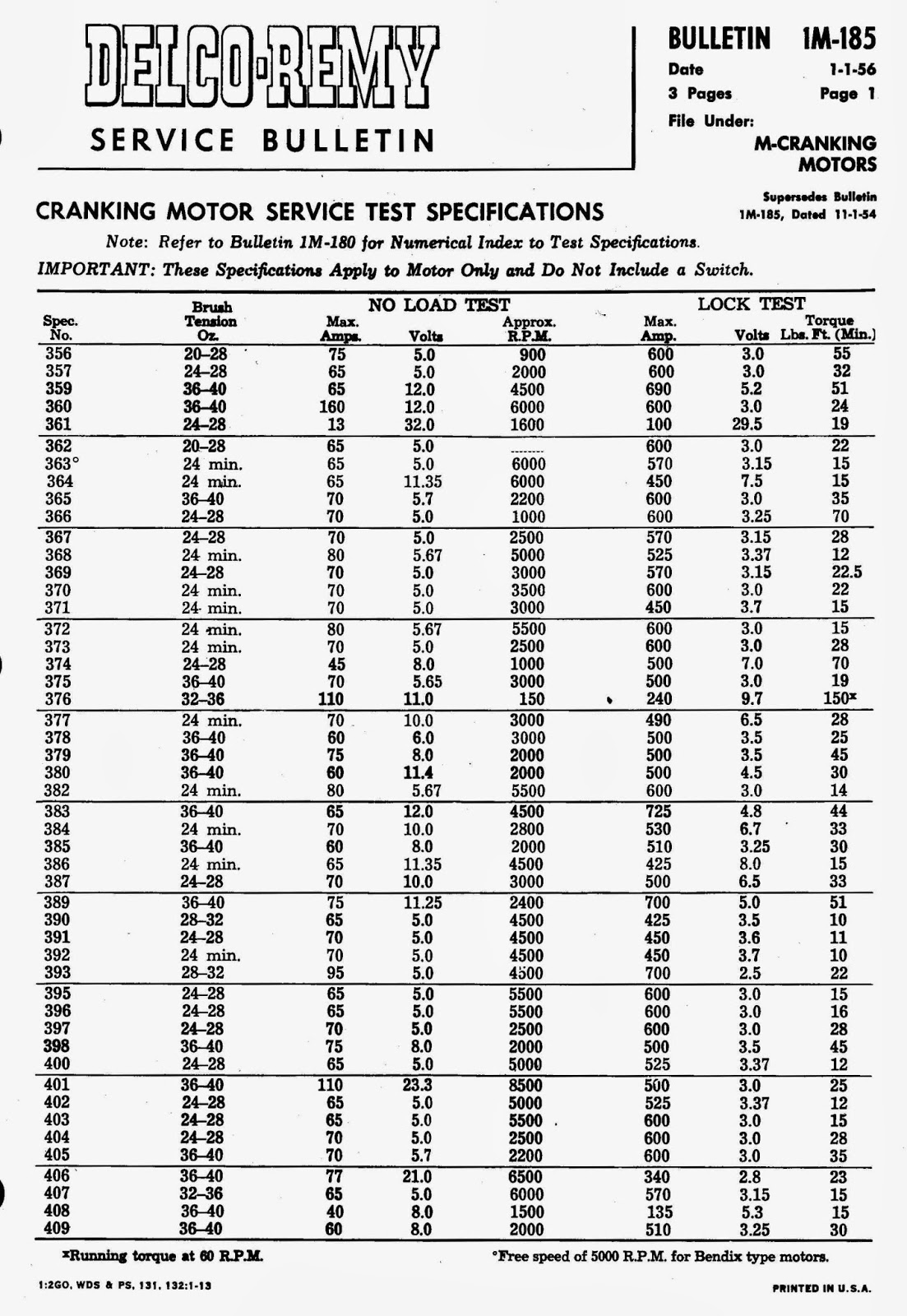
The second Cranking Motor Test Bulletin is 1M-185 Cranking Motor Service Test Specifications, 1-1-56, 3 pages.  It gives the Brush Tension, Cranking Amps, Volts, and rated RPM. as well as other information.  Spec 2377 for this starter is on page 3, below.


The Voltage Regulator used on the C-85-12 is Model N0. 118736.  The Service Bulletin for it is 1R-116 D-R 1118300 Type Two - and Three - Unit Regulators, 2-8-49, 10 pages.

The Regulator Service bulletins are:

1R-180 Numerical Index - Generator Output Control and Relay Service Test Specifications, 1-1-56, 5 pages
1R-185 Generator Output Control and Relay Service Test Specifications, 1-1-56, 10 pages.

The test spec or the 118736 Regulator is 2165 which is in Table 2 of 1R-185.

While it took several weeks to find all the Bulletins, it seems better to service the units based on the Bulletins rather than a lot of well meaning advice which may or may not be reliable.  Delco-Remy went to a lot of trouble to provide these and a lot of GM vehicles and Continental Motors were serviced using them.

Monday, February 17, 2014

Snow Damage 13 Feb 2014

 The snowstorm which came through seemed harmless when we went to sleep Wednesday night.  It was cold (25 degrees) so the snow was light.  In the morning it was still cold but what I didn't know was that in the middle of the night the snow turned to fine sleet for a while.  We ended up with about 6" of light snow, 4" of sleet heavy and some light snow on top.  About 6:20 am, while I was waiting for daylight a sudden gust of wind shook the tent enough to cause it to collapse under the weight.

 Because of the rebar I used to secure the side poles against wind, the sides leaned but did not collapse.  The wings were hanging by straps from the horizontal poles along the top of each wall.  I had also padded the poles to protect the wings from wind damage.  All of that worked to protect the wings.  In the left picture there is a bundle of poles, some plastic and some metal, above the wing.  Unfortunately when the bungee cord at the far end let go one of the metal poles struck the wing and nicked it enough to require opening the fabric to inspect and fix it.


 The right wing is just laying there on the side poles with no problems.
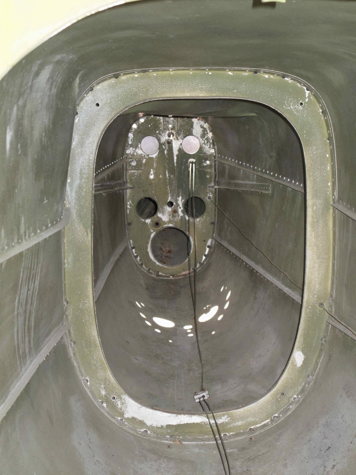
The fuselage is another story.  It took the full weight of the snow on the aft top skin of the fuselage.  The bent tent pole hit in the middle of it making a serious dent.


 There are 5 dented skin panels, the aft 2 top skins (0412116 & 0412117), the 2 long side skins (0412119 & 0412119-1) and the lower skin below the hit (0412121-3).


 Luckily the former (0412109) doesn't appear damaged.

It looks like about 70 hours work and $650 in materials to fix the fuselage.
There's another 20 hours and $200 in materials to fix the wing.

Bummer!

 Yesterday I repaired the tent, to protect things from any further damage, with a bunch of 1" EMT conduit and some bolts.
Fortunately I've kept hull insurance with Avemco to reasonably protect us if a disaster occurred.  Their adjuster will be here tomorrow afternoon to check it all out.  Hopefully this will have a happy ending.  I really didn't need more things to do and I had expected to fly the plane this summer.  We'll see what happens.

Sunday, January 5, 2014

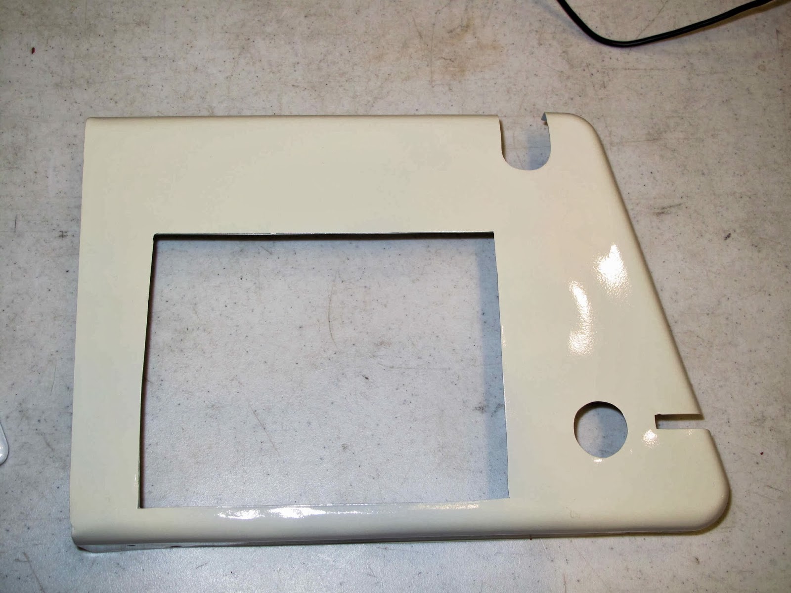
Instrument Panel Radio Cover (Left) P/N 0412492

The cover on the lower left corner of the instrument panel is for the radio. This one has been cut up twice for different size radios than the original factory opening. To fix it I've cut out an "L" shaped filler piece.  To hold it in place I've cut out a backing piece at the top and a piece of 1/2 inch angle to use on the left side. There is already an angle stiffening the left side.  This piece of angle will be riveted to it as kind of a doubler providing a place to attach the filler.

I have dimpled all the holes and riveted with flush rivets.

On this part I tried using epoxy to fill the gap. This seemed to work okay but was messy as expected. After the epoxy cured I started sanding it down to smooth it up and found there is a problem with using the epoxy. It works fine as a gap filler but it can't be as a thin layer on the surface of the aluminum.  It just peels off.  It doesn't bond well enough in a thin layer to stay there.

If I were going to do this again, I would bake the part at 225° after the epoxy has set to allow it to shrink. After the paint had air dried I put it in the oven at 225°, with the oven turned off, and allowed the oven to cool. It gives the paint a nice finish and dries it. Once this was done instead of a fine crack like you could see in the instrument panel cover there was a very slight depression where the epoxy had shrunk.

If I were trying to make the part look factory new this would be a problem. I'm trying to turn junk parts into good serviceable parts, so they are fine for what I'm doing.  You have to look to see either.

We're getting closer to being able to put all of this back into the airplane. Originally I was just can leave these parts out until I could make new ones, but I like these.

Sunday, December 22, 2013

Instrument Panel Cover P/N 0412489-3

The shock mounted portion of the instrument panel has a cover which makes it all look finished.  It also covers the light bulbs so the light can reflect into the instruments. Unfortunately someone cut it up rather badly.  It was designed to allow for adding cutouts for 2 1/4" instruments at each end of the panel.  The holes for the optional instruments were in the structural part of the panel.  One of the holes added was for a 3 1/8" instrument and the center was cut out probably for an artificial horizon.  I just want minimal VFR instruments so I need either a new cover or repair this one.  It probably would have been less work to form a new cover but I didn't have a piece of suitable aluminum so I decided to repair the old one.


 To do this I'll make up pieces to plug the holes and backing plates to hold them in place with rivets.  The first step was to trace the holes on a piece of aluminum.

 After cutting each piece was filed and ground to as close a fit as possible.  It doesn't have to be perfect as you can see from the light gaps with light shining through.
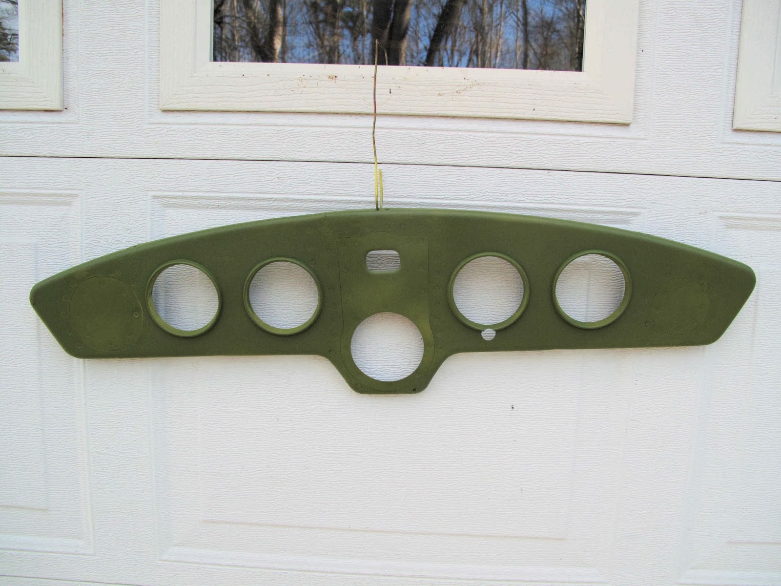
 The small hole at the top is for the compass.  The large instruments have an aluminum ring around the opening to finish the holes.  The compass hole is just rolled over on the edge.  I believe the two optional holes at the ends of the panel were finished in the same way.
To form this hole I made a form block from particle board, a clamping block to hold the metal flat while forming and a punch to form the bend.  I rounded the edge of the hole in the form with a 1/8" radius router bit.  The punch was made form a scrap piece of sledge hammer handle, from the OX-5 exhaust manifold project.

 I clamped the form block with the aluminum piece sandwiched between it and the clamping block on top.  I stood it up on the edge of a board so the hammer blows would be taken in the wood not the clamps.
The Punch was shaped fit in the hole in  the backing block and a 45 degree chamfer ground on the edge.  The wood flexed enough that I didn't need to match the radius on the form block. A couple good wacks with the 6 lb. sledge hammer did the trick.

 The finished edge of the hole looks great.

All three plugs fit.  It's starting to look like the cover again.

 I started with the end backing plates because they were flat and easy to make.  At first I thought I would need more space for riveting them in place but these are not structural parts.  I trimmed the plates closer to the plugs, as you can see in a later picture.  I punched the holes to attach the plug to the backing before punching the holes to attach it to the cover. This allows the plug to be fit in the holes to keep everything aligned while putting the holes in the cover.
The center panel needed flanges formed at the top and bottom to provide good places for the rivets.  There was also a crack in the top flange which needed to be re-enforced.  Everything was held in place with clecos until all the fitting was done.


 Originally I planned to apply some epoxy in each joint to fill the gap with somethings which would bond well in the gaps between the cover and the plugs.  I decided that was too messy.  In the end I wish I had done it since no matter how carefully I filled and sanded you can still see a very light crack in the paint at the edges of the plugs.  Hey I just want a good plane.  If it bugs me later I 'll make up a new cover, but not until the plane is flying.
I primed everything before I started puttying and sanding.


 The putty was built up and sanded in very thin layers.  I wet sanded because it works better even though you need to let it dry well before you can do the next layer.

 Before I paint I need to add the ring around the new tachometer hole.  The factory glued the rings to the cover.  They had some little tabs which they folded over to hold the ring tight.  Once the glue dried they just ground the tabs off level with the ring.  The ends of the tabs are still stuck in the glue.  The ring at the right was added by whoever cut this up.  I removed the ring and threw away the backing ring they added.  To hold the ring in the tach hole I just used a stick of wood and a big rubber band.  The stick applied the pressure to the front of the ring.  The pencil was needed to keep the rubber band from touching the back of the ring.  For glue I just used some 5 minute epoxy.  It worked great.


 The cover is held to the shock mounted panel with three clips (P/N 0412486) at the top and 2 screws at the bottom.  The clips are riveted to the cover.  They have tabs bent down with a slot for the panel to fit into.  One clip was missing and the others have cracks in the corners of the slots so I need 3 new ones.
They're made from .032" aluminum 1 - 1/2" long by 7/16" wide.  The slot is 1/8" wide and 5/16" deep.

 The rivets were originally 3/32".  The missing clip had 1/8" hole so It will just have to use large rivets.

I think the original clips cracked because because slot has square corners.  All the cracks radiate from the corners.  To help that I punched 1/8" holes at 5/16" and cut the slots tangent to the holes.  We'll see in a few year if it helps.
The rivets are set flush so I had to dimple the rivet holes,

 From the best clip it appears the tabs were bent at 30 degrees.  That's the end of a 30 degree drafting triangle.
 I used my sheet metal pliers, which I had put a nice radius on the edges.  Just square them up and bend.

Rivet the tabs on and we're ready to paint.


 I wanted a 2 tone paint job.  I have this 1946 glove box door.  In '46 they were on the left side.  I'll use it on the right side.  Since it's not in bad shape, I just polished the paint.  The white lettering is now an Ivory color.  The hardware store had Ivory paint and 6 colors of brown.  I picked the closest brown and got on with it.  I painted the rings Ivory and the cover brown.  If I were doing this again I'd paint the rings with an air brush. The spray can was too hard to control well.  To paint the Brown I propped up the cover so no painted edge would touch anything.   I masked the rings to paint the brown.  I think I could have done this more carefully but you have to look close to see where I goofed.  After the paint dried I hung the cover in an over heated to 220 degrees and let it bake while the oven cooled.  It added a nice shine to the paint.

The lower cover panels are painted with the Ivory.  I like the vintage look.