Wednesday, June 4, 2025

Plane Is In North Carolina


Yesterday Clay brought a large U-Haul truck to pick up the airplane.  His wife and son came along to help.  It took us about 5 hours to load and secure everything.  We started in the attic with the motor.  We slid it down the steps with some rope and a tow strap.

The landing gear is 90" wide and made it up the 2x10 ramps and into the truck with about 2" clearance at the door.

Out to the airport for the bulk of the parts.  Last thing in was the Stabilizer, wrapped up and strapped to the wall.


Fortunately Clay has to drive almost by on his way home from his job near DC, because I forgot that the instrument panel was on a shelf next to the motor, up in my attic.  There are a couple small parts at the airport he's going to pick-up with the instrument panel.

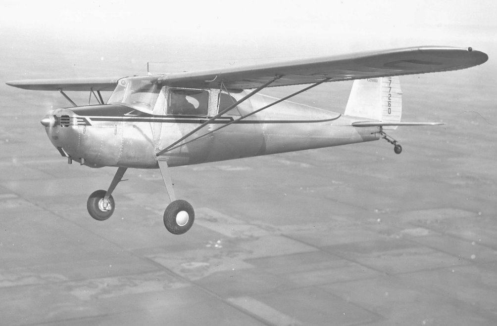
I'll look forward to him teaching his son to fly in this sweet little tail dragger.  This is one of the best Post War trainers.  What a nice plane to learn in.  Very Cool!


Sunday, May 18, 2025

Sold The Project

 I've sold the Cessna 140 project to a young fellow named Clay from North Carolina.  He's planning to bring a box truck to haul it home.  He has a 10 year old son he'd like to teach to fly in it. Awesome.


It's been fun!

Friday, August 14, 2020

Selling The Cessna 140

 I've decided to sell the Cessna 140.  It has taken much longer than I expected to get our Fly Baby back in the air.  Even now I've been taxing it but now have a leaky brake to replace, close but not quite.  I've built 2 of the 4 wing panels for the WACO NINE, which was why the Fly Baby needed to leave the attic.  I want the WACO flying for it's 100th birthday in 2026 so I need to focus on it while flying Fly Baby.  Therefore the Cessna must go.

I would like $12,000 for it as is or $5,000 without the overhauled engine.

If anyone is interested or knows someone interested please write to me.  My email address is:


wacoav8r@aol.com


It's been fun so far.  I'm sure someone will enjoy finishing this.

Friday, April 1, 2016

Work Stopped While I Get Our Fly Baby N4284C Back Flying

Our Fly Baby will be 50 years old this summer.  We finished it in July of 1966 and because we could not get an FAA inspection done in time to test fly it we trailered it to the Rockford EAA fly-in.  Pete Bowers (the designer) was there and we parked next to him.  He liked it and saw no reason not to fly it.  He talked with EAA and the FAA and all agreed it could be don.  The FAA did the inspection and at the end of the evening airshow Pete taxied out and text flew it without the crowd any the wiser.

I've decided to focus on getting it back in the air and flying it up to Michigan for my Dad to see it back in the sky after setting in my shop for too many years.

If I get anything done on the Cessna I'll post it but don't expect much until fall.  You're always welcome to read my Fly Baby Blog.

Wednesday, March 30, 2016

Priming the Fuselage


I've decided to Alodine and prime the fuselage before doing more installation work.  For primer I'll use Poly Fiber White Epoxy Primer.  I plan to shoot it with Poly Fiber's Poly-Tone for the top coats.

Tuesday, March 29, 2016

Repairs to Skin Panel P/N 0412116 (fig. 23-31)


 The center skin on the top of the rear fuselage (fig. 23-31) had 2 wrinkles, one on each side, which hammered out nicely.  Rather than replace the skin it seemed better to patch them while the other skin was removed.  I am trying to make a good flying plane not a show plane.  This is a slow process as is.

Along with these 2 patches I reinforced the stiffener on this skin and the stiffeners on the bottom skin below the one removed.  The repair manual has a repair using 0.050" x 1/2" x 1/2" aluminum angle for a stiffener.  This was done for the flanges which were slightly bent by the tent collapse.
 The first task was to drill out the rivets along one of the stiffeners.  I didn't want to unrivet too much at one time. The rivets on the formers were 1/8" and the rivets along the flanges were 3/32".
 The first step was to draw a visible center line on the flange for locating through the rivet holes.  A rivet hole was drilled at one end and the angle clecoed in place to locate the hole at the other end. Next 2 intermediate holes were marked and drilled.  The effort was to make the center line follow the rivet holes as close as possible.


 With Clecos about every 6 inches the rest of the holes were center punched and drilled.

Because the skin was still off it was easy to rivet the stiffener in place and then do the next one.

 With the stiffeners all done patches were made for the skin.  The damage area was drawn on the skin with a felt marker and then drawn on a piece of paper to lay out each patch. The damaged area was smaller on the left side.  The red lines are about where the curve start to help me form the bend in the correct place.
 The patch was cut out and all the holes punched.

To form the bend I used a piece of a heavy 3" card board tube.  A short piece of 3" schedule 40 PVC pipe would work well also.  The patch was formed around the tube by hand until it fit snug to the fuselage skin.

The patches are on the inside of the skin so holes were drilled from inside the fuselage through the skin.  As each hole was drilled a Cleco was installed to help keep the patch from moving slightly.


 Once each patch was ready to install it was primed with zinc chromate primer.

The patches were riveted in place before the aft shin was reinstalled.
 The seams on the old skin were lightly cleaned and all the joint areas primed with zinc chromate.

Ah, the fun part, my 6'-5" frame squeezed into the tail, ear plugs in place and bucking bar in hand.

Make sure your rivet gun operator is well trained before you crawl in there.  You can't see what they are doing until it's all done.

One shiny new skin in a sea of old aluminum.  Fortunately there was very little corrosion in the joints so once painted this should be good for many years more.

Monday, March 28, 2016

Forming the New Skin Panel (fig. 23-32)

For the stiffener flanges on the sides I thought I would make my own break.  It was a good idea but I could not make the bend well on a sample more than about 2 feet long.  Instead I went over to my friends shop, John Gaertner at Blue Swallow Aircraft, and used his break.  A 40 mile drive and ten work minutes to do what I wasted hours trying to do at home.  I did bend a shoe on John's break to assure the the radius would not be too small.
 I had no easy solution for the large curves rolled in the corners.  I decided I needed to form them around as large a pipe as I could to prevent leaving bend marks in the aluminum.  I tried 8" PVC pipe but it was too large.
I worked out where the bend basically started and the center of each bend on the end templates.  Then I transferred the marks to the blank panel.  This gave me references to make the bends since the radius tapers smaller from front to back.

 I like to find non-traditional uses for tools.  This may be one of my best yet.  I'm using the ShopSmith to form sheet aluminum.  I don't suppose they planned for that, but here are these nice stiff steel tubes which support the mechanism.  I was looking at the tubes thinking those are about the size of the 3 tubes used in a roller, why not use them.
My dad made a box below the tubes which catches saw dust, and tools I'm to lazy to put away.  The mechanism is opened, like when you use it as a drill press.  I slipped the piece of particle board, used while duplicating the rivet holes, under the tubes and put blocks of wood in the box to hold it snug to the tubes.
 I wedged the strip of wood under the end of the metal to help lift it.  I found it worked better with another strip of wood inside and the 2 clamped together.  I just forgot to take pictures with it clamped on.
You lift the strip of wood and control where the tubes are making the bend using the corner marks
 I found I had to wedge pieces of wood under the bent aluminum to get the radus tight enough.

Make a small bend, move slightly, and repeat.  With a little care to not over bend at any one spot, and regularly taking it out to check it against the end templates you can slowly work it to create a good fit without any evidence it was bent around the tubes.


Form one side then reverse it and form the other side.  You end up with a very nice piece ready to rivet in place.

Sunday, March 27, 2016

Making the New Shin Panel (fig.23-32 P/N 0412117)

My computer died and one thing after another it's a year and a half later and I'm finally getting caught up on postings.
 The flattened panel was used to cut a new blank from 0.032" 2024-T3 aluminum.  I cut it with the grain aligned like on the original panel from a 4 foot wide sheet.

 The flattened panel was clamped to the new blank with 2x4s to hold it flat to the sheet of particle board under the new skin.  I wanted the 2 pieces a  flat as possible to prevent misalignment of the holes.

Using the Whitney punch with the nib ground off a 1/8" punch I started duplicating the holes.  Even though everything is clamped and can't move I like installing Cleco clamps as I go to assure nothing moves.


 The nut-plate holes were then duplicated at the aft end.


 The stiffener flange on each side is 1/2" tall and the bend for it starts 3/8" from the centerline of the rivet holes.

 To punch the holes along the side the flange was cut off on the band saw.  With the ends held in place with Cleco clamps each side was again clamped to the particle board and the rivet holes duplicated.  The Cleco's helped take out any wrinkling from the straightened damage.

 The next thing was to layout the cut lines.  Graphite lead should not be used to draw on aluminum so I used masking tape to draw the cut lines.
Even if you use long smooth edge snips to trim the curved cuts it's hard not to get small wrinkles form the snips.
One way to prevent this is to make the cuts with a band saw, or table saw for straight cuts and then file them smooth.

Just make sure you mask the back side to prevent scratching it on aluminum chips


 The finished blank ready to form.
 I accidentally damaged my blank and had to make another one.  This time I cut the long straight side cuts with a Plexiglas cutter and a straight edge clamped to the aluminum and the piece of particle board.  This is a trick the aluminum siding guys use.  The cutter has a hooked blade which scratches the aluminum and then you bend and break it along the scratch.  The 0.032" aluminum is as thick as this will work with and even then it takes several passes to get the scratch deep enough to fold and break.  If the scratch is deep enough to make a bump on the back side it will bend and break.  With 0.016" aluminum 2 passes is usually enough.  It works even easier with dead soft aluminum.

Monday, October 27, 2014

Flattening Panel To Be A Pattern


With the panel removed there are 4 nut plates which need to be removed.  They're riveted on with flush rivets so there is no tool to help locate the drill except to carefully center punch the rivet.  With AD rivets it's at least easy to center the punch mark in the dimple on the head.  I find a regular center punch and hammer work better than a spring loaded center punch.

Here is a good picture of using the modified diagonal cutter to grip the upset end of the rivet to wiggle it out.

The next step was to create templates for forming the new panel bends.  I made 2 corrugated templates for each end.  One is based on the free shape of the panel and the other is the shape of the bulkhead at each end.  My goal will be to form the new part between these  2 limits.

Now I can flatten the panel to use a pattern for the new panel.  I carefully hammered out the dents better.  There is no way to completely remove the dents.  If needed the worst areas could be cut out to allow the rest of the panel to be flattened without distorting it.

I clamped the panel to the deck railing with a 2x4 and used another to push on the free end of the bend.  You just keep re-positioning it and working the bend out in small increments.  It doesn't have to be perfectly flat but close enough that it can be clamped to the new aluminum sheet while keeping the panel flat to duplicate the holes and cut lines.


With the panel flat one thing I hadn't thought about was obvious.  I would have laid out the panel so the grain ran perpendicular to the center line of the panel.  You can see from the printing it runs perpendicular to one edge to minimize waste.

I measured the thickness of the aluminum to buy the new material.  It's nice to see on the inside that the original material was 0.032" thick 24ST (now called 2024-T3) Clad Aluminum.  Alcoa created Alclad 2024 aluminum in 1931.  Before that Duralumin 2017-T4 was the go-to structural aluminum.  As a result they haven't made 2017 sheet in years.