Thursday, November 21, 2013

Switch Panel Repairs


The electrical switches on the C-140 are operated aluminum tabs, referred to as piano keys) which are located in a row just above the throttle.  It's a little complicated but it looks cool.  The fuses are located below the throttle and somewhat out of the way.

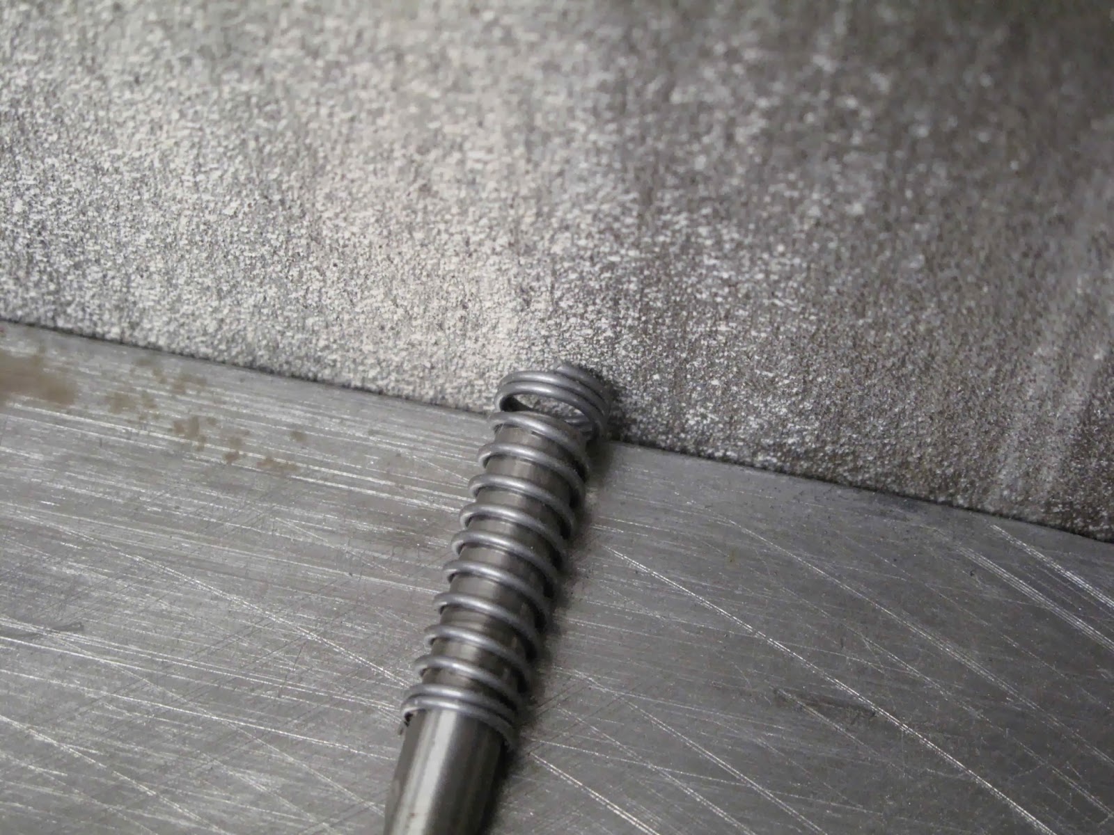
The keys are aluminum extrusions with a 1/8" hinge pin (wire).  When you push a key down it pivots on the pin and operates the switch.  There is a rubber grommet in each key to smooth toggling the switch.  It actually works just fine.

At some point the mounting brackets (0412475) which hold the pivot pin broke and someone attempted a repair.  What they did was crude but might have worked except there is a left and right hand bracket, which also hold the fuses, and they reversed them so the mounting holes don't align with the holes in the instrument panel.

Not knowing how this was all made I assumed I just needed to disassemble it all and reassemble it correctly.


After dis-assembly it was obvious more work was needed.  The repair to the brackets had been done by taking another set of brackets, cutting off the fuse area and smashing them into the broken brackets.  The little tab sticking up is for the hinge pin and that is what broke on the original brackets.


I un-riveted the repair and decided to just make new brackets from .040" 2024-T3 aluminum.

There are many ways to make such parts.  I decided to just form them using oak blocks.  By starting with a blank 9" long I left a little extra length to trim the mounting tabs to length after forming all the bends.  The mounting tabs on the 2 sides are different length.  Otherwise the left and right brackets are identical.

I punched a 1/8" hole at the center of each switch and fuse holder, then duplicated the holes on the second blank.  I'll use these holes to locate the pieces while forming the bends.


The mounting tabs will be cut out after the first bends to make it easier to control their location.


After some experiments bending the aluminum a form bloc was made with the width 1/32" less than the inside dimension between the legs.

A 1/8" radius was routed and a 7 degree spring back angle sanded on the edges of the block.

Holes were drilled and aluminum rivets used as locators to hold the blank while making the bends.  I just cut the heads off the rivets and pushed them through the holes.

Very easy to hold the blank in position.


This was clamped in the vise with a backing block to assure nice bends.

I always pound on a wooden block rather than hammer directly on the metal being bent.


Flip the whole thing over and form the second bend.  The pins keep the part from moving out of alignment on the block.

I made a little template to clamp on each side of the parts to locate the corner holes for the pin tab and the locating tabs.

Carefully cut the tabs to the holes.  The pin tab will get finished after bending the locating tabs so it's easier to work.

I made another little form block for the tabs and used some scraps to make a fixture to hold the parts while forming the tabs.


Back to the vise with this block.  I found I needed a backing block for the tabs to get good crisp bends.

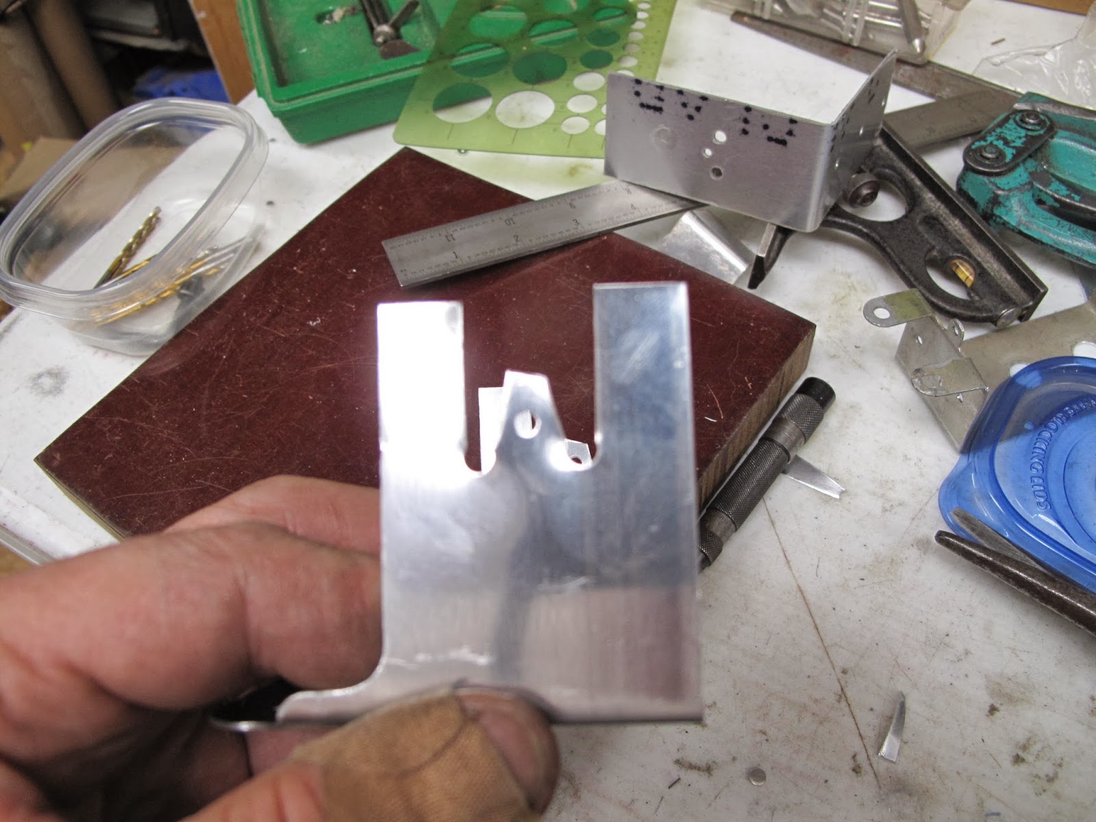
Bend one side, switch the part around and bend the second side.  Just be careful not to bend the pin tab.  I used a scrap of wood so I could see that it was clear of the tab when I pounded it with the hammer.


I punched the holes in the tabs and trimmed them.

The pin tab I made a little wider at the base on the assumption the original tabs were a little weak.  The material was just going to be trimmed off to make a square tab and this way I only needed one hole between each tab.

The switch hole are 15/32" so I drilled them with a 7/16" center drill and the reamed them with the 15/32" drill.


The fuse holder holes were 5/8" so I scribed 5/8" circles with a spade drill.

I worked the holes close with a 1/2" drill using the side of the drill to carve to holes.  I finished them with a sanding drum.

After all that work I have no idea why they made the holes so big.  I assume they originally planned for a larger fuse holder.  Oh Well.
I did find 3 fuse holders, in all the junk I have, which are for the larger fuses and they need this 5/8" hole size.  There is nothing indicating they ever used such fuse holders.

Ready to paint and reinstall.
Here is the finished assembly.  I need to wire it before I install it.  I also need to decide if I'm going to switch to circuit breakers instead of the fuses.  That depends somewhat on the cost of breakers.

I polished  the keys and waxed them.  I like it.

Now I need to make up the wiring harness.


Wednesday, November 6, 2013

Engine Baffle Fastener Springs

 To wind the springs I'm using a Porter Spring Winder which I borrowed from Rich Wilbur for our WACO NINE projects.  I measured the wire on a spring on the Fly Baby baffles and found it was .040" so I ordered some .041" music wire from McMaster-Carr.  After a little experimenting I decided to make springs with a 1" free length, 4 pounds of force when compressed to 5/8", 2 closed turns at each end, 10 open turns, and the ends ground flat.  I wound them using the 1/4" dia. mandrel.

The first step is to bend the end of the wire and lock it into the handle.

For the first 2 turns the Pitch Gauge is moved clear of the coil so the winds will be tight to each other.


 After winding the closed turns the Pitch Gauge is moved to use the smallest pitch. The farther you turn the handle the wider gap it forces between coils.  Ten turns are wound at this setting.

Then the Pitch Gauge is moved clear and 2 more closed turns are wound.


 The mandrel is about a foot long so more than one coil can be wound.

To make it easier to cut the springs apart I put a couple open turns, then started with 2 more closed turns, etc.

 I needed 8 springs and 4 fit well on the mandrel.

The wire was cut off as close to the closed coils as possible.
To hold the spring while grinding each of the ends I slipped it over a 19/64" drill, keeping the end of the drill clear of the belt sander.  The end was then ground square and flat on the belt sander.  I found it worked better if the cut off end of the wire were at the top where you can see it. Then you just grind with a light touch until the cut end is just blended smooth.


They make a spring force tester but I don't have one.  To check the force I set my vernier to extend the depth gauge 5/8" and locked it.  Then I just used the vernier to push the spring down until the end of the depth gauge just touched the table on the scale. It's not quite touching in this picture.  You can see we're right around 4 pounds with the spring compressed.  I figured out a way to use my magneto timer, buzz box, to determine when the vernier just touches the table.  You need an insulator between the top of the spring and the vernier.

All the wires and springs are made.  The 2 original wires are at the top, hooked together.

The original wires were very rusty so I decided to paint the springs and wires.

We now have all the fasteners ready to install the baffles.