Sunday, December 22, 2013

Instrument Panel Cover P/N 0412489-3

The shock mounted portion of the instrument panel has a cover which makes it all look finished.  It also covers the light bulbs so the light can reflect into the instruments. Unfortunately someone cut it up rather badly.  It was designed to allow for adding cutouts for 2 1/4" instruments at each end of the panel.  The holes for the optional instruments were in the structural part of the panel.  One of the holes added was for a 3 1/8" instrument and the center was cut out probably for an artificial horizon.  I just want minimal VFR instruments so I need either a new cover or repair this one.  It probably would have been less work to form a new cover but I didn't have a piece of suitable aluminum so I decided to repair the old one.


 To do this I'll make up pieces to plug the holes and backing plates to hold them in place with rivets.  The first step was to trace the holes on a piece of aluminum.

 After cutting each piece was filed and ground to as close a fit as possible.  It doesn't have to be perfect as you can see from the light gaps with light shining through.

 The small hole at the top is for the compass.  The large instruments have an aluminum ring around the opening to finish the holes.  The compass hole is just rolled over on the edge.  I believe the two optional holes at the ends of the panel were finished in the same way.
To form this hole I made a form block from particle board, a clamping block to hold the metal flat while forming and a punch to form the bend.  I rounded the edge of the hole in the form with a 1/8" radius router bit.  The punch was made form a scrap piece of sledge hammer handle, from the OX-5 exhaust manifold project.

 I clamped the form block with the aluminum piece sandwiched between it and the clamping block on top.  I stood it up on the edge of a board so the hammer blows would be taken in the wood not the clamps.
The Punch was shaped fit in the hole in  the backing block and a 45 degree chamfer ground on the edge.  The wood flexed enough that I didn't need to match the radius on the form block. A couple good wacks with the 6 lb. sledge hammer did the trick.

 The finished edge of the hole looks great.

All three plugs fit.  It's starting to look like the cover again.

 I started with the end backing plates because they were flat and easy to make.  At first I thought I would need more space for riveting them in place but these are not structural parts.  I trimmed the plates closer to the plugs, as you can see in a later picture.  I punched the holes to attach the plug to the backing before punching the holes to attach it to the cover. This allows the plug to be fit in the holes to keep everything aligned while putting the holes in the cover.
The center panel needed flanges formed at the top and bottom to provide good places for the rivets.  There was also a crack in the top flange which needed to be re-enforced.  Everything was held in place with clecos until all the fitting was done.


 Originally I planned to apply some epoxy in each joint to fill the gap with somethings which would bond well in the gaps between the cover and the plugs.  I decided that was too messy.  In the end I wish I had done it since no matter how carefully I filled and sanded you can still see a very light crack in the paint at the edges of the plugs.  Hey I just want a good plane.  If it bugs me later I 'll make up a new cover, but not until the plane is flying.
I primed everything before I started puttying and sanding.


 The putty was built up and sanded in very thin layers.  I wet sanded because it works better even though you need to let it dry well before you can do the next layer.

 Before I paint I need to add the ring around the new tachometer hole.  The factory glued the rings to the cover.  They had some little tabs which they folded over to hold the ring tight.  Once the glue dried they just ground the tabs off level with the ring.  The ends of the tabs are still stuck in the glue.  The ring at the right was added by whoever cut this up.  I removed the ring and threw away the backing ring they added.  To hold the ring in the tach hole I just used a stick of wood and a big rubber band.  The stick applied the pressure to the front of the ring.  The pencil was needed to keep the rubber band from touching the back of the ring.  For glue I just used some 5 minute epoxy.  It worked great.


 The cover is held to the shock mounted panel with three clips (P/N 0412486) at the top and 2 screws at the bottom.  The clips are riveted to the cover.  They have tabs bent down with a slot for the panel to fit into.  One clip was missing and the others have cracks in the corners of the slots so I need 3 new ones.
They're made from .032" aluminum 1 - 1/2" long by 7/16" wide.  The slot is 1/8" wide and 5/16" deep.

 The rivets were originally 3/32".  The missing clip had 1/8" hole so It will just have to use large rivets.

I think the original clips cracked because because slot has square corners.  All the cracks radiate from the corners.  To help that I punched 1/8" holes at 5/16" and cut the slots tangent to the holes.  We'll see in a few year if it helps.
The rivets are set flush so I had to dimple the rivet holes,

 From the best clip it appears the tabs were bent at 30 degrees.  That's the end of a 30 degree drafting triangle.
 I used my sheet metal pliers, which I had put a nice radius on the edges.  Just square them up and bend.

Rivet the tabs on and we're ready to paint.


 I wanted a 2 tone paint job.  I have this 1946 glove box door.  In '46 they were on the left side.  I'll use it on the right side.  Since it's not in bad shape, I just polished the paint.  The white lettering is now an Ivory color.  The hardware store had Ivory paint and 6 colors of brown.  I picked the closest brown and got on with it.  I painted the rings Ivory and the cover brown.  If I were doing this again I'd paint the rings with an air brush. The spray can was too hard to control well.  To paint the Brown I propped up the cover so no painted edge would touch anything.   I masked the rings to paint the brown.  I think I could have done this more carefully but you have to look close to see where I goofed.  After the paint dried I hung the cover in an over heated to 220 degrees and let it bake while the oven cooled.  It added a nice shine to the paint.

The lower cover panels are painted with the Ivory.  I like the vintage look.


Thursday, November 21, 2013

Switch Panel Repairs


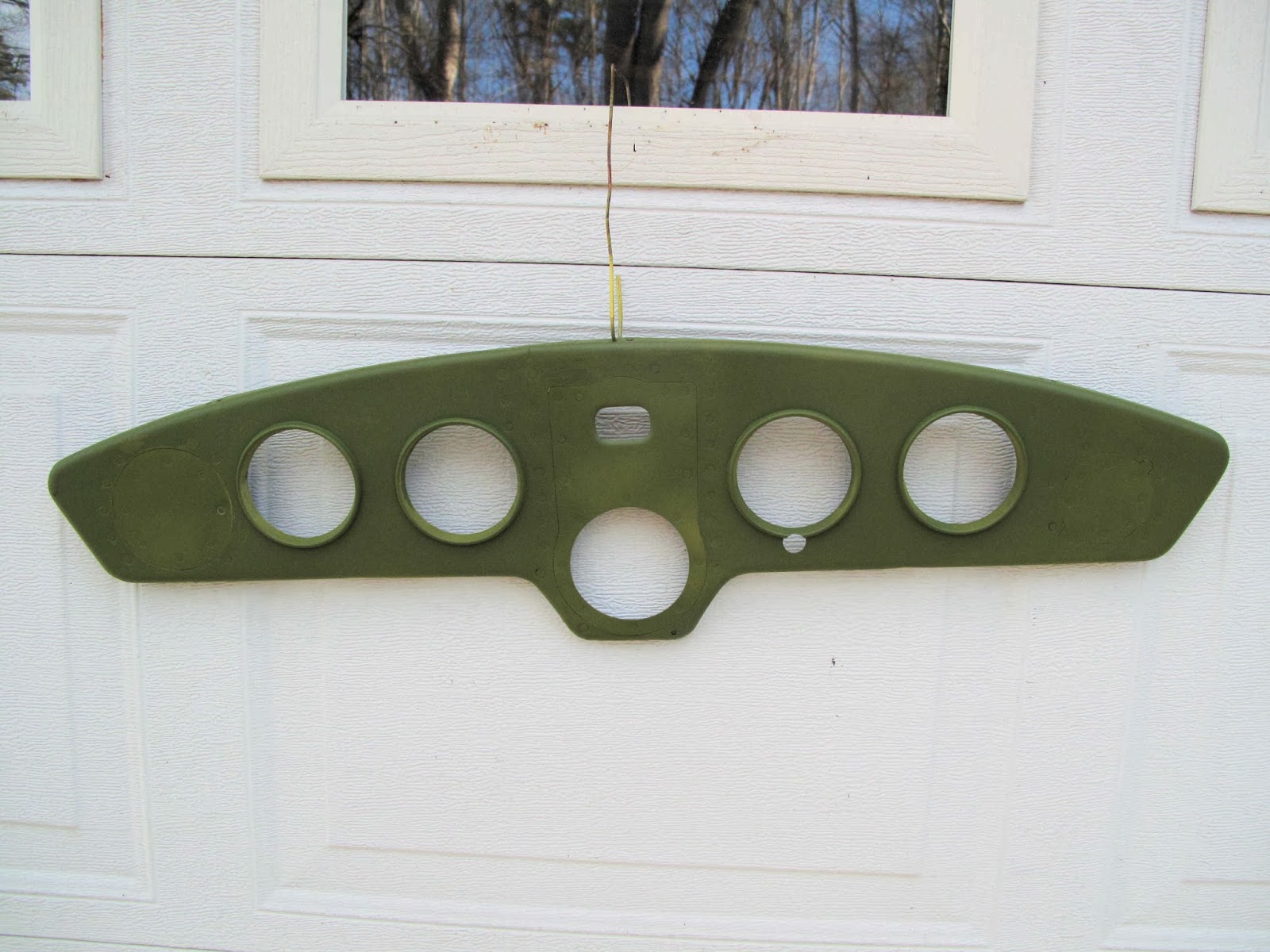
The electrical switches on the C-140 are operated aluminum tabs, referred to as piano keys) which are located in a row just above the throttle.  It's a little complicated but it looks cool.  The fuses are located below the throttle and somewhat out of the way.

The keys are aluminum extrusions with a 1/8" hinge pin (wire).  When you push a key down it pivots on the pin and operates the switch.  There is a rubber grommet in each key to smooth toggling the switch.  It actually works just fine.

At some point the mounting brackets (0412475) which hold the pivot pin broke and someone attempted a repair.  What they did was crude but might have worked except there is a left and right hand bracket, which also hold the fuses, and they reversed them so the mounting holes don't align with the holes in the instrument panel.

Not knowing how this was all made I assumed I just needed to disassemble it all and reassemble it correctly.


After dis-assembly it was obvious more work was needed.  The repair to the brackets had been done by taking another set of brackets, cutting off the fuse area and smashing them into the broken brackets.  The little tab sticking up is for the hinge pin and that is what broke on the original brackets.


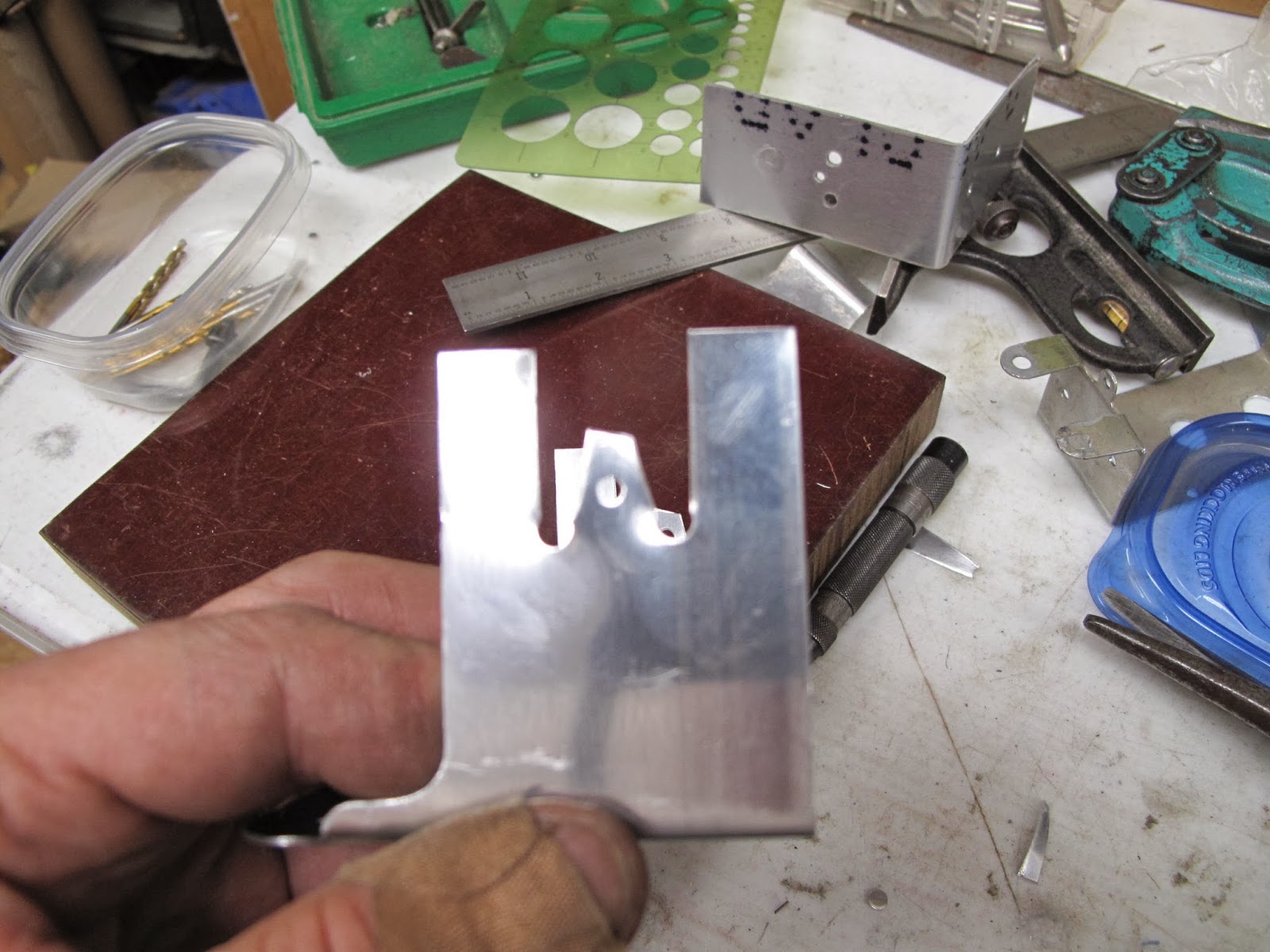
I un-riveted the repair and decided to just make new brackets from .040" 2024-T3 aluminum.

There are many ways to make such parts.  I decided to just form them using oak blocks.  By starting with a blank 9" long I left a little extra length to trim the mounting tabs to length after forming all the bends.  The mounting tabs on the 2 sides are different length.  Otherwise the left and right brackets are identical.

I punched a 1/8" hole at the center of each switch and fuse holder, then duplicated the holes on the second blank.  I'll use these holes to locate the pieces while forming the bends.


The mounting tabs will be cut out after the first bends to make it easier to control their location.


After some experiments bending the aluminum a form bloc was made with the width 1/32" less than the inside dimension between the legs.

A 1/8" radius was routed and a 7 degree spring back angle sanded on the edges of the block.

Holes were drilled and aluminum rivets used as locators to hold the blank while making the bends.  I just cut the heads off the rivets and pushed them through the holes.

Very easy to hold the blank in position.


This was clamped in the vise with a backing block to assure nice bends.

I always pound on a wooden block rather than hammer directly on the metal being bent.


Flip the whole thing over and form the second bend.  The pins keep the part from moving out of alignment on the block.

I made a little template to clamp on each side of the parts to locate the corner holes for the pin tab and the locating tabs.

Carefully cut the tabs to the holes.  The pin tab will get finished after bending the locating tabs so it's easier to work.

I made another little form block for the tabs and used some scraps to make a fixture to hold the parts while forming the tabs.


Back to the vise with this block.  I found I needed a backing block for the tabs to get good crisp bends.

Bend one side, switch the part around and bend the second side.  Just be careful not to bend the pin tab.  I used a scrap of wood so I could see that it was clear of the tab when I pounded it with the hammer.


I punched the holes in the tabs and trimmed them.

The pin tab I made a little wider at the base on the assumption the original tabs were a little weak.  The material was just going to be trimmed off to make a square tab and this way I only needed one hole between each tab.

The switch hole are 15/32" so I drilled them with a 7/16" center drill and the reamed them with the 15/32" drill.


The fuse holder holes were 5/8" so I scribed 5/8" circles with a spade drill.

I worked the holes close with a 1/2" drill using the side of the drill to carve to holes.  I finished them with a sanding drum.

After all that work I have no idea why they made the holes so big.  I assume they originally planned for a larger fuse holder.  Oh Well.
I did find 3 fuse holders, in all the junk I have, which are for the larger fuses and they need this 5/8" hole size.  There is nothing indicating they ever used such fuse holders.

Ready to paint and reinstall.
Here is the finished assembly.  I need to wire it before I install it.  I also need to decide if I'm going to switch to circuit breakers instead of the fuses.  That depends somewhat on the cost of breakers.

I polished  the keys and waxed them.  I like it.

Now I need to make up the wiring harness.