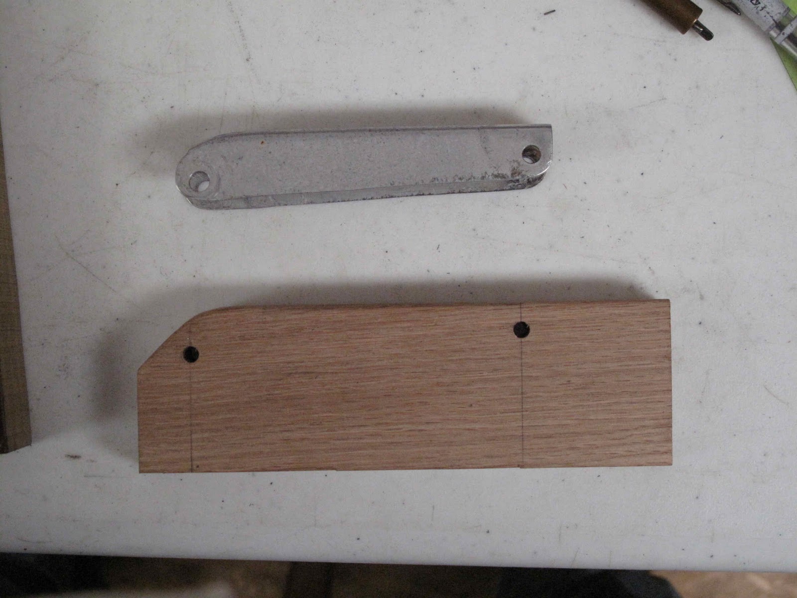
These brackets are the 2 aluminum brackets riveted and screwed to the inside of the door. They are made of .040" aluminum and are badly worn. Because they are so small and so worn, I've decided to replace them with steel parts made from .040" 4130 steel.
These are easy parts to make by cutting out a blank bending it and punching the holes. I would like them to line up with the existing holes and have the pivot hole square to help the latch work easily. The first step is to make the blanks. I prefer to make a template for every part from galvanized steel. It allows me to work out any issues without wasting expensive aircraft materials. If you are making more than one part it saves layout time. Also holes can be transferred from the template to the part so they all come out within a tolerance which make them interchangeable (remember Henry Ford).

The 2 mounting holes are 7/8" apart. Once the template is made you can check it against the holes in the door to make sure it's right. If you're not familiar with matched hole construction go read the articles in Sport Aviation on building the Thorp T-18 (Early 1960s). Matched hole construction is one of the best kept secrets of sheet metal work. Today we can accomplish this with a CNC punch press and a computer, assuming you have a couple hundred thousand dollars to spend on a press. The rest of us just use a Whitney Punch
(#5 Jr. Hand Punch) with an extra set of punches. You need to take one set of punches and carefully grind off the centering nib.
By positioning the template on the metal for the part you then carefully slip the punch without the nib into the hole in your template squeeze and punch a hole in your part. As I get each hole punched I insert a cleco clamp to help keep the template from shifting around. You will note I am not adding the pivot hole at this time. I'm good but not good enough to get them in the right spot after forming so we'll add them later.
Once the holes are punched just draw the outline with a soft pencil or a scribe. If you use a scribe just be careful not to scratch somewhere that will end up on the finished part. We don't want any cracks forming on our stray scratches. I prefer to punch all the holes I can before cutting out parts. If I mess up punching hole I don't have to throw away my labor cutting out the part, just some metal. I made some extra parts just-in-case my clever plan for forming them, etc. doesn't work out well and I think I'll use these latches for my next homebuilt project.
The parts are cut out and de-burred, ready to form.
To form the parts I cut a piece of 1/4" x 1" mild steel. Next I transferred the hole locations to it, from the template, using the 1/8" punch with the nib on it as a Center/Transfer punch. In this case there was nothing to do but carefully drill the holes using these center punch marks. I then counter drilled the back side of the form piece so I could use some 1/8" steel rivets as locater pins for bending the parts. A 3/32" radius was ground and filed on the corner of the form block and the rivets were epoxied into the holes to make using the tool easier.
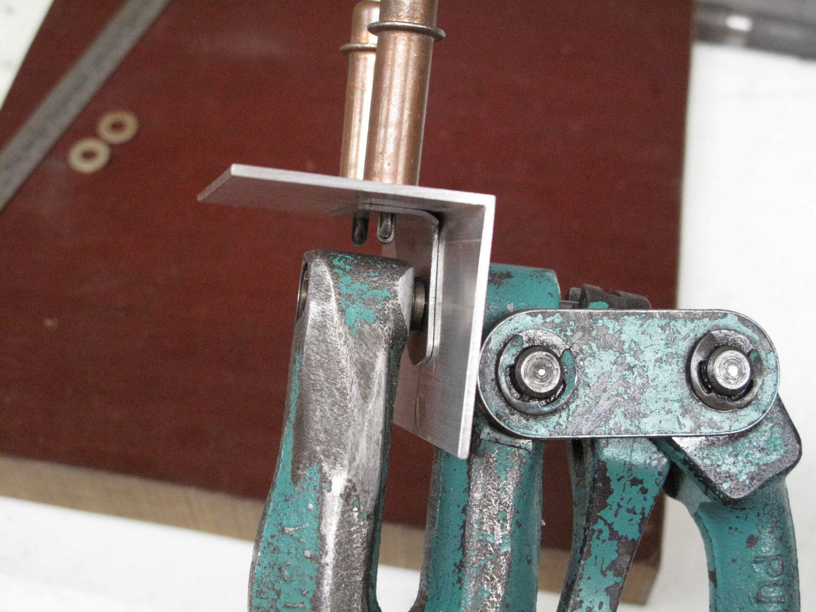
With the epoxy dried the parts just need to be slipped over the pins and the whole thing clamped in the vise for forming.
A hardwood block works fine to bend the parts over the form block. By using a narrow piece of steel for the form block the part can be slightly over bent to get the angle exactly 90 degrees.
Left and right parts are just a matter of reversing the part when forming the bend.
The next step is to locate the pivot hole in one of the parts. I used a scrap of some 1-1/2" x 1/16" aluminum angle from Lowe's for this fixture. First a line was drawn on the inside of the fixture. The top rivet hole and the pivot hole are on the same line. The top hole was transferred to the fixture so it was on the line and then the bottom hole, keeping the bent part clamped tightly to the side of the fixture. The 3/16" pivot hole was punched in the fixture. By clecoing the parts to the fixture the pivot hole can be transferred so each parts is within a tolerance that they are all interchangeable.
Then on the outside of the fixture a line was drawn through one of the mounting holes and the finished part clecoed in place. The last part was clamped in place an the mounting hole lined up and center punched on the fixture with the 1/8" punch. With that part clamped and clecoed to the first hole the second mounting hole can be marked and punched.
Now the part with the pivot hole and the mating part without can be clecoed to the fixture and the 3/16" pivot hole transferred to the second part. The parts now fit the holes in the door and the pivot holes are squarely aligned so everything will move freely. I have enough parts to do both doors, they are interchangeable and I have some spares for my next project, as well as the tools to make more.
Owner Produced Parts are really a lot of fun and easier to make than to write about.


 The finished part should work just fine. The next part to make is the steel link.


 By using these images in TurboCAD it's much easier to reverse engineer things like hole locations and the outside shape of complex parts. The drawing at the right shows the scanned images of the key parts and the assembly drawing made to check that the parts will open and fold up correctly. It helps to keep in mind that these parts were probably designed using a tee-square, triangles and a scale in 1/32" increments even though drawings were dimensioned in thousandths of an inch. To scale the images I measure some easy dimensions and adjust the scale of the image until those dimensions are correct. For the 2 links I measured the inside edge to edge distance between the 2 holes, easily done with a vernier caliper.
 The material could be no thicker than 0.040" so a piece of .040" 4130 steel was used to make the stops. The original stop appears to be loaded in bending, which make it weak, so the new stop tab was designed to be loaded in shear with a welded corner for extra stiffness (see pictures below).