This simple little Scott 2000 tail wheel which has followed me in several airplanes, Fly Baby, Taylorcraft, Champ, Cub, etc. has been quite a bundle of learning. I started with 2 complete (?) assemblies and assumed I should end with at least one good one and one re-buildable one. I have one good assembly now and a few parts. This exploded assembly drawing does not show all the parts and several parts it shows I didn't have.

Let's start with the wheel. The part at the left (12) is a felt grease seal. It has a piece of felt about 1/8" thick trapped between a washer and a dish shaped piece which is rolled on the edge to trap the felt and washer. The felt needs to be oiled. I'll get to that later. The ones I had were both so warn that there was no felt sticking out into the hole for the shaft. As a result neither would provide any seal to keep the grease in, and keep out dirt or water. They had probably been that way for a while since all the bearings were shot. The rolling surfaces of the races were furrowed like a plowed field. I'm shocked the wheels didn't shake to high heaven.

The next part has no call out but is a felt grease seal under the hub cap. I made mine with 3 layers of 1/16" felt glued together. I made it that thick because the boss on the wheel for holding the seal centered is that tall. I made the O.D. 2-1/2" to clear the screws for the hub cap. To get it to seal out dirt and water I worked wheel bearing grease into it. Just push it down over the boss and the hub cap squashes it down into a nice seal. Speaking of wheel bearing grease. The grease called out for the tail wheel is AN-G-15 which is a general purpose grease not wheel bearing grease.
For the seal on the other side of the wheel the part comes from Univair without any oil. There is only about 1/16" of felt sticking out from the metal housing so working grease into it didn't seam a practical idea. What I really wanted was for it to be well oiled. After all grease is just a carrier with oil added. It's the oil that does the work of lubricating. I thought of just soaking it in oil but wasn't sure it would get further in than just the little bit of felt sticking out. Instead I soaked it in 200 degree 5W30 motor oil like an Oilite bearing. The coolest thing happened when I added the bearing to the hot oil. The air trapped in the felt expanded and blew out so after soaking it about 15 minutes I just removed the heat and let it cool to room temperature to draw in as much oil as it could.
I didn't find and obvious wear or play in the Bracket (1) bushing (4) for the Fork (5) spindle so not much to say there. I have no Idea what the acceptable limits for this are.
The next part at the top of the tailwheel is the magical Arm and Cam assembly (6). It is riveted together so normally no one opens it. One of mine had been opened and reassembled with screws by threading the lower plate. The other assembly snagged when moving the arms so both were taken apart. I'm glad I did because the screwed together one had the better parts but some were missing, never good.
The missing parts were the 2 little spacers I made in an earlier posting. The first picture shows all the parts inside with the lower bushing installed as well as the 2 spacers. Inside the housing are 3 bronze bushings, 2 spacers and 2 arms. The bushings are all identical and the arms are left and right based on the bend tipping the arm up slightly. The stack-up of parts is: bushing, left arm, bushing, right arm, bushing. The spacers which hold the covers solid also act as stops for the 2 arms.
When the arms are aft, straight out, the shaft hole is open and the tailwheel swivels freely. Without the springs holding 25-30 pounds on the end of the arms there is no steering.
When the arms are held forward by the springs the hole becomes sort of triangular shaped which matches the angled slots cut in the spindle of the fork. That little clamping force on the spindle is what allows the steering. If you push the tail to the side the spring load on one side releases and the arm moves to open it's half of the hole and the tailwheel starts to swivel freely.

The arms in the assembly have to line up with the slots in the spindle so they made shims to put between the bushing in the bracket and the face on the fork as the bushing wears down. I have one shim but it was not needed to line all this up correctly. The last piece which I just figured out, and have none of, is a spacer which goes on top of the end of the spindle. It allows the nut to be properly torqued while maintaining the needed clearance for everything to move. It also provides a bearing surface for the top of the Arm and Cam assembly. I'll see if I have one on the Fly Baby which I can copy or if I need to make 2 of them.
The tail wheel is back on but I still can't sign it off until I solve this last problem.


 I've removed the tail wheel now that the plane is back on the mains. I think I'm shocked at the neglect. It has been so long since being greased that the grease had dried out back to paraffin. Grease is made by melting paraffin wax and adding #30 oil to the mix and letting it cool. It takes a very long time to dry out this bad in a closed space like the wheel or arm and cam assembly. Fortunately the plane came with 2 tail wheel assemblies. Like all steel parts the springs were rusty but they cleaned up fine. One tire is dead and the other is serviceable. The wheel bearings are all shot. I'll save one set as an example of just how bad bearings can get. The inner races on one wheel are like furrows in a plowed field. I've found new Timken A4050 bearings on e-bay for about $55 shipped so hopefully they really are new as advertised. The rest should be a matter of cleaning, painting, greasing, and new hardware. I'll have to fabricate new rubber pads for the springs. I have some 70 durometer rubber which should work fine. The tubular rubber piece which goes around the bolt in the spring holes is fine so that's good news. I should have everything ready by the time the bearings arrive. This is the same tail wheel we have on the Fly Baby so any serviceable spare parts will always be welcome.
 After a rainy day yesterday it finally cleared this afternoon. The last wedge went in fine. This would have all been easier using a 7/16" universal socket. It's shorter than a socket and a universal joint, all 1/4" drive. There is not much space to work.
 As the sun sets it's nice to have it starting to look like a plane again. Now I can get the remaining control cable pulley brackets out to clean up, re-grease the pulleys and check all the cables. All the brackets are rusty so I'm sure I'll find more problems but they should all be minor.
 The gear is finally back on. I still have 3 rivets to install on the skins around the gear. They need some modified bucking bars to get them in and I need to crawl in the fuselage to figure out what is needed. I haven't wanted to crawl in until the plane was off the stand. The rivets are also easy to get at with the gear on. I still need to install one of the wedges and torque the 2 attachment bolts.Someone had modified the skin on the left side to get at the wedge bolts better. I did those 2 wedges first without realizing how much easier it was with some room to work and being able to see what was happening.
 The right side has not been modified and is tough. On top of that the slight amount of primer I put on the gear, 2 coats, prevents the wedges from going in as far as they did in the factory. This requires longer bolts which adds to the problem. I did not repaint the wedges for that reason and wiped off any primer on the channels with MEK. The wedges are a very shallow taper so it doesn't take much to make a big difference. I got each wedge lined up with the bolt hole and then started the bolt in to assure it would be lined up free to turn it in. Then I pounded the wedge in tight per the Cessna 100 Series manual and tightened the bolt. Once I was convinced I had the wedge as far as it would go I checked the bolt with the mirror and found I had 1 - 2 threads through the nut plate, perfect. I don't trust that the wedges are in as far as they should be since I used AN4-10A bolts and the parts list shows AN4-5A. The bolts I removed were AN4-6A, but even then 1/4" longer bolts leaves me believing the wedges can go in further. I'll recheck them as we move forward and also after we start flying just to see if they can be wedged in further. I quit when it got dark and I got tired. It's still very cool to have the gear back on.


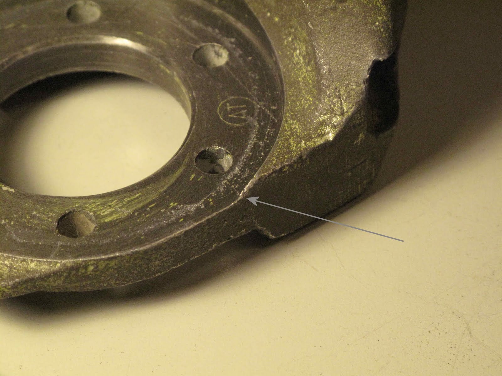

 The new brake lines are fabricated and installed in the gear box. It took a few hours of careful work to get them so they follow the correct path and attach where they are supposed to. Fortunately 1/4" tubing is easy to work with.
 I'm priming the fuselage under the 2 skin panels before I rivet them back on. After the riveting is done the gear can finally go back on.
 While removing the landing gear legs I had a problem removing the 2 bolts holding the wedges tight on the left side. The nut plates and bolts had rusted enough to bind the bolts and shear the rivets holding the nut plates. The bolts came loose enough to get the wedges out before I realized there was a problem. I should have gotten some oil on them before I started removing them. I had no problem on the right side but they were also rusty.
 The nut plates are riveted into the steel channel which is the upper gear support. I needed to get in enough to replace the nutplates on both the right and left gear. It also seemed a good chance to clean up any light rust and re-prime as needed. I thought about trying to remove the floor above the supports but removing the skin piece (0411611) covering the area was easier. I'll also replace the short piece of brake line which looks like it gets wet from water around the gear leg. Most of what looks rusty there is really primer sprayed in through the leg hole in the past. The bolts were easily cut off with a Dremel tool with a cut off disk. Now I know what to use to cut off a lock. It really went quickly through the 1/4" AN bolt.
.
The next step is to clean things up, epoxy prime and put in new nut plates. It looks like the skin can be riveted with the gear leg installed, but I'll probably rivet first.
 All the parts are painted ready to reassemble, after the paint drys a little more. New brake pads had been installed so I have new o-rings, felt seals and bolts. The wheel bearings will be repacked. It will be nice to put this plane back on it's own legs.
 Business has finally slowed enough to get back to the landing gear. All the parts are cleaned and the first coat of epoxy primer sprayed.
 I found a nice little airbrush at Michael's craft store for $25. It is set up to work with expensive little air cans. With a piece of 1/8" tubing and a couple fittings I modified it to work with the air compressor or my little portable air tank.
 Both wings have now been sanded and resprayed with Poly-Spray. If the weather holds I'll start spraying color with Poly-Tone.
The gear legs are cleaned up and the step rivet holes inspected for cracks, fortunately none were found. I've sprayed the first coat of epoxy primer on the legs. I like epoxy primer better than zinc chromate. They'll get one more coat before putting them back on the fuselage.
I have 2 sets of wheels and brakes with the project, one set of Goodyear and one set of Cleveland. We'll try using the Cleveland assuming they clean up to be serviceable. I've started bead blasting the parts to remove paint and corrosion. At least the rotors cleaned up fine.
 The past three weeks have been very busy in the embroidery shop. Things have slowed enough to get some time on the fuselage. It's been to cold to spray on the wings. We may have to move them back up to the attic for the winter. Most everything has already been removed from the fuselage. There are a few steel parts which need to be removed and repainted, rusty. The gear legs are one of those and it seemed better to start there. We needed to remove them to properly clean them and epoxy prime the metal.
 To remove the gear you need to get at the main bolt in the fuselage. The Bolts that hold the wedges in are easy to get at from outside. The wedges jam the spring steel tight in the frame so the legs don't rattle around on landing. To hold up the fuselage and get the doors open the easiest place to support it is at the rear spar attach fittings, behind the doors. Two 2x4 rails were laid on the ground and vertical pieces cut to fit over the spar fittings. Diagonal braces were added to stabilize the posts and everything is screwed together. I put a bolt through the 2 cross braces just to make it more rigid.

 .
 With the doors open it was easy to get to the bolts. You need a 3/8" allen wrench for the bolt and a 12 point 9/16" wrench for the nut. A little tapping on the inside of the gear leg with a soft mallet got the wedges out and then it's just a matter of sliding the leg out. I thought I might need to support the gear but they don't move once the bolts are out.
 The mains are off and in the shop for cleaning and painting. I'll also clean up the wheels and repack the bearings so once it's all done we won't need to take any of it apart before the plane flys.