Monday, October 27, 2014

Flattening Panel To Be A Pattern


With the panel removed there are 4 nut plates which need to be removed.  They're riveted on with flush rivets so there is no tool to help locate the drill except to carefully center punch the rivet.  With AD rivets it's at least easy to center the punch mark in the dimple on the head.  I find a regular center punch and hammer work better than a spring loaded center punch.

Here is a good picture of using the modified diagonal cutter to grip the upset end of the rivet to wiggle it out.

The next step was to create templates for forming the new panel bends.  I made 2 corrugated templates for each end.  One is based on the free shape of the panel and the other is the shape of the bulkhead at each end.  My goal will be to form the new part between these  2 limits.

Now I can flatten the panel to use a pattern for the new panel.  I carefully hammered out the dents better.  There is no way to completely remove the dents.  If needed the worst areas could be cut out to allow the rest of the panel to be flattened without distorting it.

I clamped the panel to the deck railing with a 2x4 and used another to push on the free end of the bend.  You just keep re-positioning it and working the bend out in small increments.  It doesn't have to be perfectly flat but close enough that it can be clamped to the new aluminum sheet while keeping the panel flat to duplicate the holes and cut lines.


With the panel flat one thing I hadn't thought about was obvious.  I would have laid out the panel so the grain ran perpendicular to the center line of the panel.  You can see from the printing it runs perpendicular to one edge to minimize waste.

I measured the thickness of the aluminum to buy the new material.  It's nice to see on the inside that the original material was 0.032" thick 24ST (now called 2024-T3) Clad Aluminum.  Alcoa created Alclad 2024 aluminum in 1931.  Before that Duralumin 2017-T4 was the go-to structural aluminum.  As a result they haven't made 2017 sheet in years.

Saturday, October 25, 2014

First Damaged Fuselage Skin Panel Removed


 Originally I planned to build a particle board fixture to support the fuselage while I worked on replacing the skins.  I assumed I needed to remove the long 0.025" panels on the sides of the fuselage which would leave the fuselage very weak.  After hammering out the wrinkles in the 2 top panels I could see the side panels were not damaged and did not need to be removed.  I also kept worrying about the rain warping a wood fixture.

Instead I've decided to use one of my 6 ft. long plastic tables tipped so the fuselage bottom sets flat on it while the front of the fuselage is supported by the main gear.  As it worked out I raised the tail end with a piece of 4x4 post and then shimmed the nose end to a snug fit.  I folded a packing blanket for padding to protect the underside of the fuselage.  By only replacing one panel at a time I think it will work fine.


 To remove so many rivets I purchased a Rivet Removal Tool from ATS.  I thought about making such a tool but they had exactly what I would have made and for less than $60.  The tool has a drill in it which extends through a tube which fits snugly on the head of the rivet.  It comes with drills and tubes to fit 3/32", 1/8", 5/32" and 3/16" universal head rivets.


 You adjust the tube so the drill just penetrates to the bottom of the head.  That way you don't damage the skin.  The knurled nut locks the tube to hold its length.  You need to hold the barrel while drilling so it stays securely on the rivet and does not spin.  If it spins the lock not will not hold the tube and the drill depth will change.  OK, I didn't ruin anything but I'm smarter now.  Did I mention there were no instructions with the tool.  I guess they thought it was as obvious as I did.
 It doesn't perfectly center the drill so don't attempt to drill deeper than the rivet head.  It does do it better than my best efforts with a center punch and guessing at the depth.

One thing I've learned removing rivets is that when the rivets are set the shank expands slightly to fill the hole securely.  This is part of how they provide strength.  When riveting in thin sheet metal this can lock the rivet into the sheet.  Trying to pound it out will bend and damage the sheet.

A better solution is to switch, after drilling the head, to the next size smaller drill, and drill just through the depth of the sheets being held together by the rivet.  This will allow the remaining tin walls of the rivet to loosen their grip on the sheets.  For the 1/8" rivets along the sides of the fuselage I switched to a 3/32" drill and set the drill to extend about 0.050" - 0.060" beyond the end of the tube.  Using the 1/8" rivet tube/stop re-drill all the rivets to the new depth with the smaller drill.  The stop prevents drilling through the upset end of the rivet.  For the rivet where there is also a bulkhead in the stack the depth has to be set that much deeper, etc.  This method will allow about 80% of the rivets to be punched out with a spring loaded center punch.  By carefully drilling the rest with a 7/64" drill until you just feel it hit the bottom of the hole you'll loosen most of the rest of them.
 To remove the heads just stick a 1/8" pin punch in the hole, tip it off center and the heads pop off.  That's the safest way to prevent scratching the skins.  If that won't remove it you can use the pin punch and a hammer to carefully push the head off sideways.

 For the few rivets which won't pop out with the spring loaded punch, I bought a cheap pair of diagonal wire cutters and ground the back side down to the point of the cutting edge with the belt sander.  Also round any sharp edges.  Now you just grip the upset end of the rivet with the cutters, rotate and pry it out.

 While I've been removing rivets I've been installing Cleco Clamps in every other hole to hold things in place until I'm ready to remove the panel.

With the rivets removed a little wiggling got the panel out.  It fits under the side panels and under the panel in front of it.

Now I need to fabricate a new panel from 0.032" 2024-T3 clad aluminum.  Fortunately the material information is printed on the inside of the panel.  I'll install the new panel with the printed side in for the next person.

Friday, July 11, 2014

Wing Struts Primed


The grandkids, Rowan & Duncan, are visiting so it was a great excuse to get back to working on the plane.  We're learning how to hold the can an even distance from the part and to start and stop spraying while the can is in motion.  A light coat, let it dry 10 minutes and another light coat.  With 2 struts there was plenty for each.  The weather was warm and dry so the struts baked in the sun all afternoon.  We used the wing stands to hold the struts so we could rotate them.  It made spraying much easier.

Well done young apprentices.

Sunday, March 16, 2014

Electrical Loads & Wiring

Much of the electrical wiring in the Cessna was stripped out before I purchased the plane.  I have a lot of wires in a card board box.  None of them have anything identifying where they go.  All the wiring is with the old cloth wrapped insulation.  Before I can repair the wiring I need to understand what should be there.  The wire list (figure 43 in the IPC) has almost all of the individual wires.  It also lists the old Sta-Kon part number for the terminals, but it does not give a clue to the wire gauge.
The 120/140 Club has a nice Simplified Wiring Diagram for the 140.  Unfortunately it does not give a clue to wire sizes either.  It's also for a 1946 C-140 and mine is a 1947 model.  The differences are small like the fact that in '47 they added a rheostat to dim the panel lights and, a sub-panel for the 2" engine gauges & clock which has 2 lights, while the shock mounted panel went from 3 to 4 lights.

The wire size depends on the Voltage, Current flow (amperage and whether it is a Continuous or Intermittent flow), Fuse size (if appropriate), Length of the Circuit, Ambient Air Temperature around the wire, and whether the wire is in the free air (good cooling) or in a bundle of other wires (which limit cooling of the wire).  This is starting to sound complicated.  It also depends on the aircraft operating altitude, less than 20,000 feet, so that's easy anyway. I had to go back to a 1976 revision of AC65-15A, Figure 11.8 to find out that Intermittent means in use for a "maximum of 2 minutes".  You can do something like installing a placard which says to limit use of the landing light to 2 minutes or less, if needed, to keep the wire to a reasonable size for a load where it could be, but doesn't need to be, on continuously.

Using the Simplified Diagram all this breaks down into circuits for:
- Engine Ignition  -  No Fuse
- Master Switch Solenoid  -  No Fuse
- Starter  -  No Fuse
- Power Bus  -  No Fuse
- Generator - 15 amp fuse with 12 amp Generator
- Navigation and Cockpit Lights, Plus Landing Light Motor - 10 amp fuse
- Landing Light Bulb - 25 amp fuse
- Electric Turn and Bank  -  10 amp fuse
- Radios  -  10 amp fuse

- Grounding

Before we jump into the details, one issue I'll deal with later is to assure there is adequate ground (bonding) between the all the various parts of the plane and engine.  Without a path for the return current flow to the battery (negative ground) all the rest of this is useless.

- Engine Ignition

The Engine Ignition circuits just ground the magnetos so there in no significant current flow.  These were easy to identify in the pile because they were shielded to suppress radio interference.  They're 18 gauge wire.

- Master Switch Solenoid

The Master Switch does not turn on the power directly.  It operates a solenoid which connects the battery positive cable to the starter and from there to the fuses.  The coil in the solenoid is connected to the Battery Positive cable post with a short jumper wire. When you operate the Master Switch it grounds the other end of the coil to operate the solenoid.  This means this circuit is active Continuously when the Master Switch is on.  Great but how much current does this coil draw?  No one seems to know or care.  Cessna Service Bulletin SB 65-89 allows the R-57 solenoid to be replaced with an S-1579A2 which Aircraft Spruce sell.  I've written to them for an answer for their solenoid.  Until I find the truth I've estimated it at 0.5 amps.  The total circuit length is about 12 feet so a 16 gauge wire will do.  It's in a bundle of 3 wires in the rear of the firewall at 70 degrees F (20 C) so we're still good with 16 gauge.  In fact a 16 Gauge wire this long, etc. could handle up to 6 amps so we're not close to a problem.

- Starter

I've read a lot of discussions on the 124/140 forum about the starter cable.  I have an old parts catalog showing the various Mil Spec fabric jacketed wires and cable made by Prestolite.  They give a dimension over the insulation for each to make identification easier.  The cable I have measures 0.353" diameter which is the diameter for 4 gauge Cable.  Number 2 gauge is 0.424" and 6 gauge is 0.294".    Because it's a stranded cable you can't just measure the wire diameter.  You have to measure the diameter of the strands and calculate the total cross section area to determine the cable gauge.  My old cable has 7 bundles of 19 wires (7x19).  Each wire strand measures 0.018" in Diameter (25 gauge).  This makes it an ASTM B173 Class H rope lay up creating a 4 gauge cable.  There was some discussion on the 120/140 forum about whether this cable was a 3 gauge cable.  There technically is such an animal.  If it's made with the same 7x19 layup it uses 24 gauge (0.021") strands.  There is no doubt my old cable is a 4 gauge cable.  There is no way to know if it's the original factory cable but it's age and everything says it probably is.

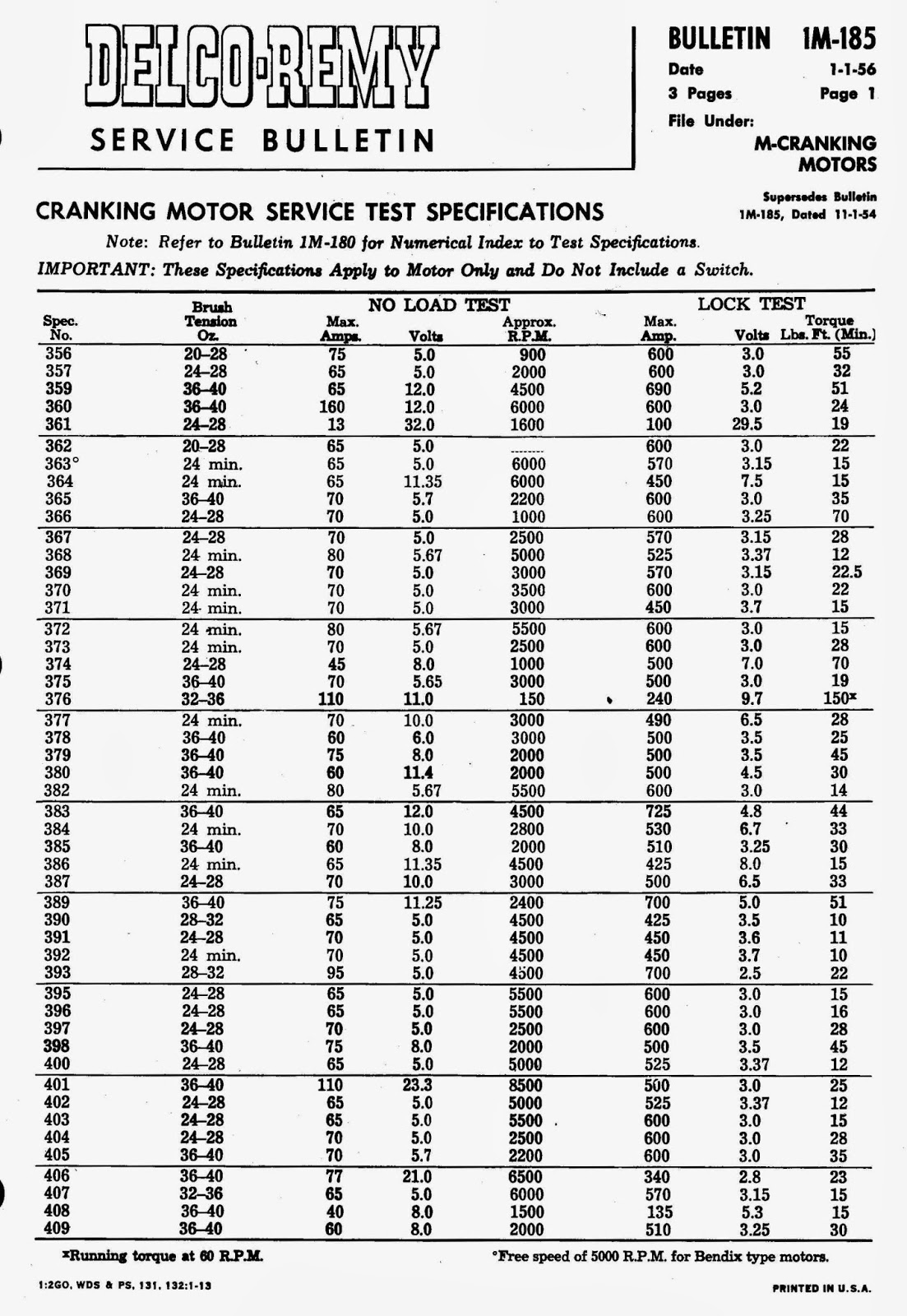
Assuming this is a 4 gauge cable let's look at the load to see if this works. The cable is 12 feet long.  So how many amps does the starter draw?  According to Delco-Remy Service Bulletin 1M-180, Cranking Motor #1109656 draws 65 amps when tested at 11.35 Volts, turning 1200 RPM with No Load.  If it's locked (held so the rotor can not spin) it draws 450 amps when tested at 3.9 volts and should produce at least 60 Ft. Lbs. of torque.  The estimates I've read for a normal cranking load vary from 150 amps to 300 amps.  I think 150 amps would be a reasonable estimate for a hot, well worn engine.  I also think 300 amps would be a reasonable estimate for a tight fitting cold engine.  The starter is also limited to 30 seconds of operation to avoid overheating, so it's definitely intermittent operation.  Per AC 43.13-1B you need to limit the wire to a 1 volt drop for an intermittent 14 volt circuit.  Including 1 ft. from ground to the battery and 1 ft. from the battery to the solenoid, this line is 14 ft. long.  The formula is easy E=IR (Voltage drop = Current flow x Resistance).  The resistance of a 4 gauge wire is 0.28 ohms / 1000 ft. (per AC 43.13-1B, Table 11-9).  Therefore at the maximum drop of 1 volt a 4 gauge cable will be carrying 255 amps.  I think I'll stick with the 4 gauge cable.  If we change to a 2 gauge cable, it could handle 397 amps. but it would be much stiffer to route through the various bends ( as discussed on the 120/140 forum).  The new 4 gauge cable from Aircraft Spruce (Mil-W-22759/16-4) is a much stiffer cable.  It is wound with 19 bundles of 7 wires (19x7).  The math is simple, they both use 133 wires of 25 gauge, but the stiffness is amazingly different.  The old cable bends very easily by comparison, just like extra flexible control cable which is also a 7x19 cable.

- Power Bus

The starter cable also provides power to the rest of the airplane's electrical systems.  From the battery cable stud on the starter a wire runs to the Ammeter and on from there to the Fuse Holders, effectively the 14 volt Bus.  This wire powers everything except the Master Solenoid and Starter.  When everything is running and all radios transmitting this creates a 14.9 amp load, which is less than 80% of the Generator output.  I realize the normal load is lower than when the radios are transmitting but I don't have all those loads.  When the landing light is on this load jumps to 34.1 amps.  To cover these loads this wire needs to be a 10 gauge wire.

- Generator

To keep the battery charged the Generator provides up to 20 amps.  The original Generator (Delco-Remy #1101876) only provided 13 amps at 15 Volts (per D-R Bulletin IG-185 pg 4).  The armature circuit for the generator was fused with a 15 amp fuse.  Nothing shows a higher amperage fuse for the 20 amp Generator  (Delco-Remy #1101890) or a different size wire to handle the higher current flow.  In fact nothing shows the 20 amp generator was actually used on the plane.  The airplane Type Certificate Data Sheet A-768 shows only the small generator.  The problem is that the generator is part of the engine Type Certificate.  It's Data Sheet E-233 shows 4 generators Delco-Remy Models 1101876 (15 Amp ?), 1101890 (20 Amp), 1101879 (25 Amp), and 1101898 (35 Amp).  The 15 and 20 amp units both weigh 10 lbs. so there is no weight and balance change and the field winding on the 20 amp generator  draws slightly less current 1.58 to 1.67 amps vs 1.62 to 1.69 amps for the 12 amp (per D-R Bulletin 1G-185).

The real difference comes with the Armature and Battery circuits.  The Battery circuit to the Voltage/Current Regulator is the line with the 15 amp fuse.  This is also the line which feeds current from the generator back to the 14 volt bus to keep the battery charged.  The generator field winding is powered from the Regulator.  After much research I found that on later planes Cessna used a 15 amp fuse with the 12 amp generator, a 20 amp fuse with the 20 amp generator and a 35 circuit breaker with the 35 amp generator.  Per AC 43.13-1B Table 11-3 you need at least a 12 gauge wire with the 20 amp Fuse, so that's what I'll use for all the generator circuits.  I'll also relabel the fuse holder to show the correct 20 amp fuse.

If anyone has a 120 or 140 with a generator larger than the 12 amp model I would check the fuse, wire gauge and weight and balance to make sure all of it is correct.

- Lights

The lights are easy.  The electrical loads and wire lengths, etc. are such that the 10 amp fuse requires heavier wire, 18 gauge, so that's what I'll use.

Tail Nav. Light - Bulb 1777 - 1.52 amps at 20 feet
LH Nav. Light - Bulb 1512 - 1.5 amps at 22 feet
RH Nav. Light - Bulb 1512 - 1.5 amps at 21 feet
Panel Lights - 6 Bulbs 1826 parallel wired - 0.72 amps at 4 feet
Dome Light - Bulb 1826 - .12 amps at 8 feet
Landing Light Motor - Up or Down - 4 amps at 15 feet

The landing light bulb is wired directly to it's own 25 amp fuse.  Because of available wire sizes Table 11-3 does not show a 25 amp fuse.  It jumps to a 30 amp fuse which requires a 10 gauge wire so that's what I'll use.  Again the other factors don't require it to be heavier.

- Electric Turn and Bank

The electric Turn and Bank gauge is on a 10 amp fuse which requires 18 gauge wire.  The parts manual shows a 2 amp circuit breaker between the fuse and the instrument.  Geoff, my electrical engineer friend says 10 amps would fry it, so I'll find a place to install the breaker.  There doesn't seem to be a hole so it may not have had it originally.

- Radios

The radios originally had a 15 amp fuse.  The radios I plan to install call for a 10 amp fuse so I'll change it to that and relabel it.  I'm using wire sizes for the radios per the installation instructions.

I think I have all the wire and connectors so it's time to repair wires and assemble the new harnesses.

Wednesday, February 26, 2014

Generator and Starter Manuals

One of the things I've been trying to do with this project was to do everything according to the correct manuals, service letters, etc.  When I got ready to work on the starter and generator I realized I didn't have the manuals for them.  The starter, generator and voltage regulator were made by Delco-Remy and used on a lot of small Continental engines so I assumed the manuals were easy to find.  I went to the C-140 club library but no luck.  I then checked the forums but again no luck.  I tried all kinds of on line searches using the part numbers, etc.  I eventually found a web site for people working on old Chevy's and things went quickly after that.  
Each year Delco-Remy published a collection of Service Bulletins in an Electrical Equipment Operation and Maintenance Handbook.  This book is number DR-324.  They also published a separate collection of Service Bulletins with the Test Specifications needed to do the actual tests, repairs, and adjustments.
On January 1, 1956 they published a version of these 2 books which collected all the prior annual versions of this information into 2 books so you didn't need all the individual prior year copies.  After that they published annual updates again.  Prior to the 1956 edition the individual Bulletins were only updated as needed.  As an example I found the 11-20-49 version of DR-324 on line.  The Generator Operating Principles Bulletin 1G-100 in it is dated 1-22-46 which superseded one dated 12-28-38.
I couldn't find the test spec book on line and finally purchased a 1956 copy from a company in Israel.  It came by mail in about a week

For the Generator there are 3 bulletins.  I've shown the first pages of each here.  The three are:

1G-100 Operating Principles Generators, 7-22-46, 4 pages
1G-125 Types and Designs of Generators, 12-16-46, 6 pages
1G-150 Adjustments, Test and Maintenance of Generators, 2-4-49, 12 pages


To test the generator there are 2 Service Bulletins.

The first is 1G-180 Numerical Index - Generator Service Test Specifications, 1-1-56, 7 pages.  You use this one to look up the specific generator model number to find the applicable specializations in the second bulletin. On the C-85-12 the generator model number is 1101890.  It's near the bottom of the first column of page 2, below.  It shows that the test spec to use for this model is 1814, the generator turns clockwise, and the brush spring tension is 24 ounces.

The second Generator Test Bulletin is 1G-185 Generator Service Test Specifications, 1-1-56, 6 pages.  It gives the Field Current, Output Amps and Volts at the rated RPM. as well as other information.  Spec 1814 for this generator is on page 5, below.

For the starter (Cranking Motor) there are 4 Service Bullletins:

1M-100 Operating Principles - Cranking Motors, 7-24-46, 4 pages
1M-120 Cranking Motors Using Overrunning Clutch Drive, 8-30-46, 4 pages
1M-130 Cranking Motors Using Dyer Drive, 9-9-46, 4 Pages
1M-150 Adjustments, Test, and Maintenance of Cranking Motors, 3-2-49, 13 pages


To test the starter there are, again, 2 Service Bulletins.

The first is 1M-180 Numerical Index - Cranking Motor Service, 1-1-56, 4 pages.  Again, you use this one to look up the specific starter model number to find the applicable specializations in the second bulletin. On the C-85-12 the starter model number is 1109656.  It's near the bottom of the third column of page 4, below.  It shows that the test spec to use for this model is 2377 and the starter turns clockwise.

The second Cranking Motor Test Bulletin is 1M-185 Cranking Motor Service Test Specifications, 1-1-56, 3 pages.  It gives the Brush Tension, Cranking Amps, Volts, and rated RPM. as well as other information.  Spec 2377 for this starter is on page 3, below.


The Voltage Regulator used on the C-85-12 is Model N0. 118736.  The Service Bulletin for it is 1R-116 D-R 1118300 Type Two - and Three - Unit Regulators, 2-8-49, 10 pages.

The Regulator Service bulletins are:

1R-180 Numerical Index - Generator Output Control and Relay Service Test Specifications, 1-1-56, 5 pages
1R-185 Generator Output Control and Relay Service Test Specifications, 1-1-56, 10 pages.

The test spec or the 118736 Regulator is 2165 which is in Table 2 of 1R-185.

While it took several weeks to find all the Bulletins, it seems better to service the units based on the Bulletins rather than a lot of well meaning advice which may or may not be reliable.  Delco-Remy went to a lot of trouble to provide these and a lot of GM vehicles and Continental Motors were serviced using them.

Monday, February 17, 2014

Snow Damage 13 Feb 2014

 The snowstorm which came through seemed harmless when we went to sleep Wednesday night.  It was cold (25 degrees) so the snow was light.  In the morning it was still cold but what I didn't know was that in the middle of the night the snow turned to fine sleet for a while.  We ended up with about 6" of light snow, 4" of sleet heavy and some light snow on top.  About 6:20 am, while I was waiting for daylight a sudden gust of wind shook the tent enough to cause it to collapse under the weight.

 Because of the rebar I used to secure the side poles against wind, the sides leaned but did not collapse.  The wings were hanging by straps from the horizontal poles along the top of each wall.  I had also padded the poles to protect the wings from wind damage.  All of that worked to protect the wings.  In the left picture there is a bundle of poles, some plastic and some metal, above the wing.  Unfortunately when the bungee cord at the far end let go one of the metal poles struck the wing and nicked it enough to require opening the fabric to inspect and fix it.


 The right wing is just laying there on the side poles with no problems.
The fuselage is another story.  It took the full weight of the snow on the aft top skin of the fuselage.  The bent tent pole hit in the middle of it making a serious dent.


 There are 5 dented skin panels, the aft 2 top skins (0412116 & 0412117), the 2 long side skins (0412119 & 0412119-1) and the lower skin below the hit (0412121-3).


 Luckily the former (0412109) doesn't appear damaged.

It looks like about 70 hours work and $650 in materials to fix the fuselage.
There's another 20 hours and $200 in materials to fix the wing.

Bummer!

 Yesterday I repaired the tent, to protect things from any further damage, with a bunch of 1" EMT conduit and some bolts.
Fortunately I've kept hull insurance with Avemco to reasonably protect us if a disaster occurred.  Their adjuster will be here tomorrow afternoon to check it all out.  Hopefully this will have a happy ending.  I really didn't need more things to do and I had expected to fly the plane this summer.  We'll see what happens.