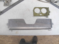
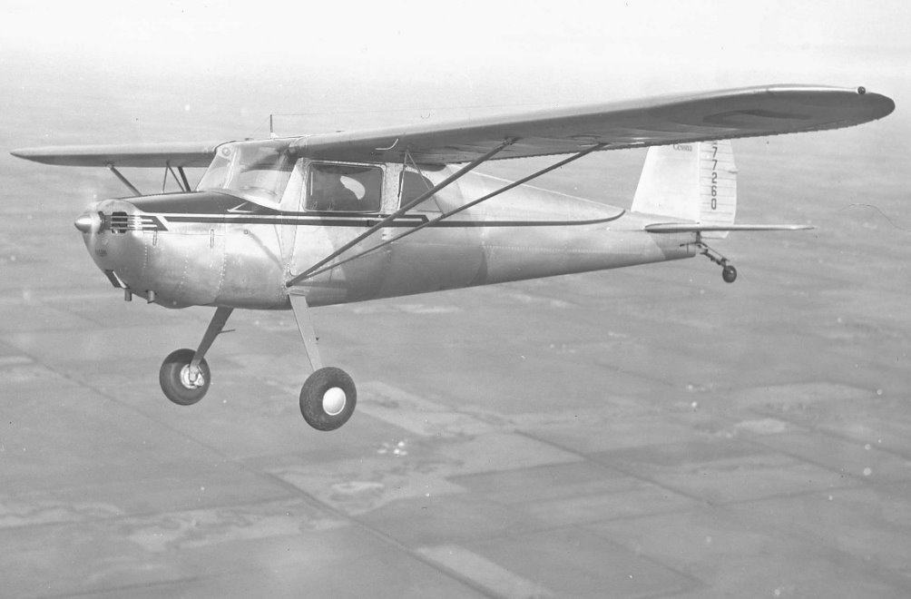
Someone removed the Pilot side handle (passenger side shown) to make room for a large instrument at the end of the shock mounted panel. The 2 end instruments were originally 2 1/4" size and only used as options. The handle was stamped from .040" aluminum.
My first effort was to just hammer out one. I made a form block which includes the curve of the instrument panel. The idea was to anneal the aluminum, draw it part way, then re-anneal it and repeat as needed. It would probably work if I could anneal the aluminum better. They make markers to use to control the temperature. I did it with the simple method of coating the aluminum with soot and then heating until the soot disappears. It worked pretty good but I don't think I got it evenly heated. It probably works better with a bigger torch.
You can see it was forming fine but it always ripped open on the second pass. Clearly I need to learn more about this process.
I decided instead to make the part from 3 pieces and gas weld them together. The center part I formed using some blocks of 1x2 and clamps for a break. I also left it a little short on depth so I could stretch it a little after welding to work harden it.
I made the center part the full length so I could cut it down to fit the end pieces.
Before I made the end pieces I decide to stop and learn to gas weld aluminum. I have a few books on the subject and some videos. How hard can this be? I recently took a refresher course on gas welding steel but the instructor knew nothing about gas welding aluminum. He was into TIG welding aluminum. I have no money for a TIG welder. For things like this I can work easily on the little deck outside my attic shop. Unlike 4130 steel a slight breeze isn't a big deal. The bucket has warm water for scrubbing off the flux which is very corrosive.

My first tries were pretty bad. To much heat, moving to slowly, very erratic and lots of holes. Nothing I read or watched really showed the weld puddle up close. You need good light so you can see the texture of the surface as it just darkens slightly and gets rough looking almost like a cold solder joint. As soon as that starts to happen the edges of the metal start to swell up slightly and separate. That's when the rod, which is being held just at the edge of the flame so it's hot but can't melt, gets pushed into this start of a puddle. Pull out the rod, back off the flame and you have a tack weld. Of course that assumes you cleaned the parts,clamped them so they are tight together and fluxed just along the seam as well as the rod.

On this thin (.040") aluminum you need tacks every 1/2" - 3/4". As you weld you need to back out the flame about every 1/2" to keep from over heating the joint. It's actually just like soldering on copper foiled stained glass work. You have to get everything hot enough for the solder to flow onto and between the copper foiled edges of the glass. Get it just a little to hot and the solder runs out the bottom. I'm sure with practice you can get so you just keep welding the full length of the seam by moving the heat in and out as you go. Once my welds got this good I was sure I could do this well enough to make my part. I had welded about 10' - 12' of seams at this point. I'm not ready to weld a gas tank but I know I can do it with more practice.
To make the end pieces I first annealed a piece of aluminum and folded it with about a 1/2" radius so it would fit in the form block.
To hold it down while forming the piece I clamped a file handle into the form block. I pounded it in with a hammer to give the bottom the curved shape I wanted, then I clamped it down. This prevented the metal in the bottom from being stretched to much.
By hammering the flat part down starting at the outer edges, with a rawhide mallet, you get a nicely wrinkled part. The wrinkles on this one are perfect. After annealing you just start at the outer edge of the outside wrinkle and start working inward flattening it. This shrinks the metal making it thicker while flattening it.
I don't need it perfectly flat at this point. Once its welded it will be nicely annealed around the weld. I can anneal the flat areas and finish flattening them. The 2 end pieces were band sawed and smoothed with the belt sander to give a very straight edge. They are not parallel. I'll trim the center piece to fit these. Also the seam is between rivet holes so no rivet goes through a seam.
The first end is welded to the center. I welded on the bottom side because it was easier the welding onside the handle.
Now the welded assembly was trimmed to fit the other end piece.
All 3 pieces are now welded and well cleaned to get rid of the flux.
The welded assembly goes back into the form block to have the handle form finished. It also hardened the metal. The flat areas at the ends were also hammered flat on a thick piece of aluminum to smooth them and harden them.
The top 3 side of the handle go under the skin around the handle. The bottom flange goes on top of the panel edge that the skin is attached to so it needs to set higher. By clamping a strip of aluminum under that flange the rest of the part is hammered down to create the offset.
With a little trimming and punching the rivet holes the part is done. I'm going to paint it before I install it since it is not made of a corrosion resistant aluminum. It fits perfect and once installed you'll be hard pressed to even notice it's not original. I've got several more aluminum welding projects ending with a new gas tank for the Fly Baby.
 The primary instruments are on the oval shock mounted panel (1). The ammeter, clock, oil pressure and oil temperature are on a stationary (not shock mounted) panel (20). This panel is screwed to the back of the large panel (72) which is riveted into the fuselage structure. This makes a simple mount for the gauges and makes a nice box for lighting the gauges. Unfortunately someone cut off most of the panel, for reasons I wouldn't even attempt to guess. At least there was enough to figure out how it was made.


