Saturday, January 30, 2010

Riveting Ribs To Spar

The ribs are riveted to the spar. I modified the long head of my rivet squeezer to fit loosely over the spar flange. There may be some heavy rivets it won't squeeze without bending but I mostly use it for 1/8" and 3/32" rivets so I don't think it will hurt it. The biggest problem I had was my rivet gun hasn't been used in years and the air valve was stuck. I also discovered that I do so little riveting I don't own any bucking bars. With 9" of snow falling I faked it and moved on. The skin below the tank is riveted to the spar and we're ready to set rivets on the skin and the drag wire brackets. Then the outboard skin can go back on. This was a very long day of going slow and careful. I don't want to have to redo this.

Friday, January 29, 2010

Riveting Spar

I've started riveting the new spar, etc. I could have started this earlier but I wanted to make sure everything fit properly. I've started with the compression members. Then I'll do the ribs and the skin below the tank. I'll get everything I can before the skin goes on. The drag wire brackets will have to wait until the skin is on the spar because the brackets block the rivets above them. I'll trammel the wing before I finish the skin. Well, that's the plan anyway.

Thursday, January 28, 2010

Bending Leading Edge Skin

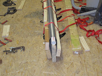
The best way to do this is with a press brake where you push the sheet into a die to form a nice bend at the exact location needed. I don't own a 12 ft press brake. I've faked it where the skin is narrow and long by folding it and pressing it between 2 2x4s screwed to the floor. I just didn't think I had the strength to do that with such a wide skin. The plan here is to form it by pulling the skin down over a tool made by screwing a length of 1" schedule 40 PVC pipe to the edge of a straight 12 ft long 2x8. The screws were spaced about every 18", countersunk and any edge of the head sticking out filed smooth with the pipe.
You can see in the first picture with the old skin setting on the tool showing what the desired shape should be.
.
.
To keep the skin from becoming wavy and to protect the edge of the skin, 12 ft long 2x4s were clamped, with backing blocks, to the skin edges.
.
.
With the 2x4s clamped on, the skin was placed over the tool with the nose of the Leading Edge ligned up with the top of the pipe, red marks on skin and pipe.
.
.
Light crank type cargo straps were than wraped around everything about 2 ft on centers. OK, this took about 10 tries because the 2x8 wants to fall over. By holding the 2x8 with my knees while carefully starting to tighten the 2 straps at each end I eventually got it going. I then realized I should have used a 2x8 on the long side and started over with some extra 2x4s so it would all clamp closer to the bend. .
Eventually the bend was tight enough that the clamps and backing blocks were hitting on the 2x8 preventing further bending. We were able to remove the clamps and blocks at this point because the friction of the 2x4s against the skin prevented them from slipping. If I had some pieces of 2x2 to add right at the bend I could have made this bend even tighter.
As it turned out it is not as bent as the old skin but it is identical the the skins I recently installed on some Cub wings with no problem so they should work just fine. Once they're riveted to the spar and top of the nose ribs the straps can be used to pull the bend tight to finish the underside riveting.

Tuesday, January 26, 2010

New Leading Edge Skin

The first task was to fit the old skin back on the wing to make sure all the holes still align correctly so it can be used as a pattern for the new skin. Again Cessna did an excellent job making the parts the same. Everything aligns perfectly. While the skin was on I also marked any holes which needed to be ignored or had gotten elongated drilling out the rivets. There were extra holes from drilling out the welds. If a hole was elongated an arrow was drawn on the skin to show which side of the hole to use as a guide when punching the new hole (see the 3rd picture below). After a careful cleaning of the floor the sheet of aluminum was laid out and 15" cut off for the new shin. Because this was thin enough sheet I used a Stanley knife and padded straight edge to score and break the sheet, much cleaner than snips. On thicker sheet like spar webs I use the table saw, noisy but very clean straight cuts. By standing the strip on edge in a curve it is stiff enough to allow easy filing of the edge to clean it up and debur it. You can see some of the markings to help punch new holes correctly. Because of the curve of the old skin I'll work from the inside so all the markings need to be transferred to the inside of the skin. X's mark holes to ignore. The old skin was then clamped to the back of the new skin. The only place I have that is flat is the floor so some 2x4s were used to hold the skins off the floor far enough to work with the Whitney punch. C-clamps and craft sticks, to protect the metal, were used to hold the shins from moving while new holes were punched. I started with the 3/32" holes between the ribs along the spar. They were generally the cleanest holes. As holes are punched clecos are installed and the clamps removed. These are simple matched hole construction methods. Go on line to the EAA Sport Aviation library and look up John Thorp's articles on building the T-18 in the early to mid 60's. Always punch any hole you can reach with the Whitney punch using a punch with the center nib carefully removed. Holes that can not be reached are center punched with a duplicating punch and drilled using the old skin as an added drilling jig to help keep the drill bit from wandering. I will do the holes from the other edge after the bend is made, the skin is fitted and alignment holes located along the other edge.

Monday, January 25, 2010

Primed Nose Ribs

The 4 nose ribs which needed some minor repairs are fixed. All the nose ribs and the outboard leading edge skin are epoxy primed. With the ribs installed the old leading edge needs to be fitted on to make sure it can be used as a pattern to make the new leading edge skin.

Sunday, January 24, 2010

New Spar Installed

All the areas where corrosion was removed or cleaning exposed bare aluminum were treated and primed. The spar is now ready to install. Suprisingly the new spar went in easier than the old one came out. Everything fit perfectly and all the holes align. Clearly a testament to how they made the parts and assembled the wings at Cessna. The only rivets which will be oversize are due to old repairs. The most I'll have to do is clean out any primer in the rivet holes and we'll be good to go. With clecos in everything and the drag wire installed the wing is back on the stands until we start riveting. The front drag wire fittings have to be removed to rivet the leading edge to the spar, so it will be back on the tables for that. Until then, the ribs and outboard leading edge have been cleaned and are ready for primer. There are 4 nose ribs which need minor repairs and we'll be ready to fabricate the new Leading Edge. The aluminum is due in 2 days so the nose ribs should be on before the leading edge is ready

Friday, January 22, 2010

Removing Front Spar

I realized I have several 2'x4' plastic tables from Sam's which we use in the shop and for our booth at fly-ins. They are adjustable for height from 24" to 36" so they make nice work tables. Three of them nicely support the wing. After rem0ving the clecos I gently worked the spar loose. With a stool as a support at the root end the spar came off easily.
There was a little corrosion hidden at the area around the tank bay which was where the corrosion problem was. This wing spent to much time parked on its nose. Who knows, a critter may have nested in there at one time while it was stored. It all cleaned up easily from the surface of the ribs, etc. It shows the protection difference of the clad aluminum used for the ribs and the bare extruded spars. I'll treat and prime the cleaned areas so they'll last and hope all the holes match up with the other spar.

Thursday, January 21, 2010

Rivets Removed From Front Spar

The first task was to remove all the nose ribs. They need to be cleaned up and treated for minor corrosion and make some repairs. The rivets are now all removed from the front spar so it can be removed. Clecos have been installed to hold it all together while removing the rivets. The wing is now more like a limp flag. I've been able to use my wing stand so far but I need to make some stands or a large table to hold the wing while I swap the spars.

Wednesday, January 20, 2010

Prime Spar and Finish Leading Edge

Today the rain stopped and it warmed up to 41 degrees. Well, the can of epoxy primer says it will paint and cure down to 35 degrees and if it's humid just let the primer set for an hour instead of 30 minutes. As you can see most of the 14" of snow is finally gone. The primer went on just fine after a final wash with MEK just to make sure it was clean. A few hours later the rain was back but by then the spar was safely back in the attic to finish curing.
By evening the primer was dry to the touch and the attic is only 55 degrees. The leading edge is now off. Removing and cleaning ribs is next. I've tagged the ribs to put them back in the same positions because I want to use the old skin as a pattern rather than mark and drill all the rivet hole from scratch.

Tuesday, January 19, 2010

Removing Leading Edge on Right Wing

Today was rainy so priming the spar will have to wait.

Today I put the wing back on the stands and started unriveting the leading edge. I didn't want to take the wing apart until the spar was ready to install because an assembled wing is easy to strap to the ceiling in the shop. I think I ran out of storage space a year ago.

Most of the rivets are 3/32" and are very easy to drill off the heads. What I hadn't thought about was the spot welds. The leading edges were originally welded to the ribs. It seemed like a good idea but the welds broke at high angles of attack and high loads so they went back and added rivets. Even with my careful drilling of rivets I won't be able to reuse the leading edge, which is in good shape, just to many holes with rivets and welds.

The welds seem to come apart best by center punching the middle of the weld and carefully drilling with a #30 drill (about the size of the weld spot) while lifting the skin until the weld lets go. Some were already broken years ago. Some brake as soon as you lift the skin a little, and other need to be drilled. You don't have to drill away all of the weld for it to weaken enough to let the skin break lose. You want to leave some skin on the rib since the skin is going to be replaced and the ribs can be cleaned up and reused. We'll clean up the ribs after they're off the wing.

Monday, January 18, 2010

Cleaning up Corrosion on the Front Spar

Now that all the rivets and fittings are off cleaning the light corrion and remainging crud on the spar is easy. First I washed off any remaining paint residue with MEK. To clean the corrosion I glass bead blasted with AC beads at 20 psi. Glass beeds can be sieved and re-used up to 30 times if you keep the pressure low enough not to smash the beads, and blast at a 45 - 60 degree angle so you're scrubbing the surface not just peening it. When I first bought glass beeds the young lady selling them explanied that the pressure should be very low, if you can see something happening it's probably to high. This was slow work but well worth it to make sure there is no corrosion trapped and growing under the expoxy primer when we're done. Also, you're only blasting any spots of surface corrosion. This is a 53 year old spar so there was a fair amount even if nothing serious. The biggest problem was how to get a wing spar in my blasting cabinet. There is a door on one side so I put a metal cutting blade in my circular saw and cut a hole in the other end of the cabinet so the spar could pass through (this will also work for grit blasting the wing struts). I then took some scraps of a stiff foam rubber and made plugs for the holes. I cut the plugs about 3/4" large than the holes and split the edge of the foam so it fit over the edge of the metal making a nice seal. I adjusted my roller stands for my table saw and placed one on each side of the cabinet for the spar to roll on. Next I cut "I" shaped slits in the foam for the spar to pass through laying on it's side. Problem solved, no mess in the shop, put on a head set with something to relieve the boredum and blast away. The spar really cleaned up nice. With the cleaning done the spar was treated with a Phosphoric Acid Etch & Brightener, and then a Conversion Coating to assure no corrosion is left and the primer bonds well.

Sunday, January 17, 2010

Removing Rivets From Front Spar

Todays task was to finish removing rivets from the front spar. When it was removed from the wing the rivets were drilled just enough to get the ribs off leaving all the holes plugged with the ends of the rivets (I'm not complaining). For the 3/32" rivets holding the leading edge and ribs a light tap on the drilled off end with a hammer and punching them out with a pin punch worked fine and quick. For the 1/8" rivets in the doubler at the strut fitting I drilled them with a 3/32" drill most of the way through the spar and the punched them out with the pin punch. They just hung up to much with 3 layers of metal to punch out otherwise and I didn't want to increase any hole sizes. I also removed the strut fittings and the drag wire fittings. They'll have to go back on after the ribs are riveted on.

Saturday, January 16, 2010

Stripping Wing Spar

We're finally done with end of year tasks in the business and the snow is starting to melt. With the temperature at a warm 51 degrees I got the spots of paint and primer stripped off the front spar. Clearly stripper works better at 70 degrees. I used a stiff propylene brush and a lot of elbow grease and it cleaned up nicely. I wanted to make sure someone hadn't painted over some light corrosion. It seemed better to clean it all up now while the spar was easy to work on.

Saturday, December 12, 2009

Brought The Engine Home

Today I was at a breakfast in the Shenandoah Valley and was able to stop at Bill's house to get the engine, windshield and some other small parts. The machining is all done for the overhaul and some assembly has been done. The plan now is to disassemble the engine to make sure nothing has corroded while it's been setting and then reassemble it complete. A very good winter project. I won't even need to turn on much heat in the attic workshop. The cylinders were done by Buldoc Aviation at Anoka County Airport in Minnesota. We've been busy with the Christmas rush in our embroidery business so the wins have been setting.

Sunday, November 29, 2009

Control Surface Paint Stripping

Today was one of the perfect fall days here in Virginia. The dog and I spent the afternoon outside. He slept while I stripped paint from one aileron and one flap. It looks like Bill had decided not to use these. The aileron needs a little work and we have one spare new old stock flap. The aileron looks easier to fix than the spare we have which has a little corrosion. I think I'll sell the spare flap when I'm done. I'm assuming the better one will bring more money. The used ones are in very good condition. They do need new piano hinges, but those will be easy enough. At least with spares I have alternatives if things don't work as planned, does anything?

Saturday, November 28, 2009

New Right Wing Spars

Today on my way home from visiting the grandkids in New York I stopped to visit Bryan Cotton in Elmira. He is also rebuilding a Cessna 140 and had a set spars which he did not need for his wing. As a result I now have a new (used) set of spars so I can start rebuilding the right wing. I'll need to clean up the spars and epoxy prime them before I start taking the old wing apart.

Thursday, November 19, 2009

Picked Up Control Surfaces

Met with Bill today to get the control surfaces, engine cowl, struts and other small parts. It was a rainy day but very exciting. There are enough extra parts that we should soon have all the control surfaces inspected, repaired and ready for primer.

Inspection Rings

Installed 2 inspection rings aft of the rear spar on the left wing per Cessna Service Letter 39A. Waiting for warm dry weather to continue with this wing.

Wednesday, November 18, 2009

All Fabric Clips on Left Wing

The clips are finally done. Not bad once you know what you're doing and fix someone else's mistake. With clips that closely spaced it really looks secure. The closer spacing on the upper surface is required per Service Letter 42. Without them the plane is not allowed to do aerobatics or fly in extreme turbulence. Ok, I can live without flying in extreme turbulence, but it is nice to know the fabric is well attached. The upper side has 139 clips and the lower side has 68. As a double check to make sure I didn't miss any, the Cessna parts manual says you need 207 per wing. The lower side of the wing took about 1-1/2 hours to apply the twill tape, melt the holes and install the clips. The only problems were with the thicker metal due to the landing light mounting.

Tuesday, November 17, 2009

Fabric Clips

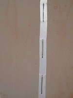
Today was a learning day. That means a simple project took way to long but now I think I understand why. I started with great expectations of how quickly fabric clips could be installed instead of rib stitching. The first three went well and the the next ones wouldn't go in and if they did they popped back out on one end. Not very good for that secure feeling you need flying on turbulent days. That really makes a nice clean hole and eliminates snagging in the twill tape. Time to stop and see what I could learn from Jim & Dondi. Jim had a great suggestion which helped. I took my cheap soldering iron, 25 watt, and pointed the end to melt holes in the twill tape and fabric. It helps to have a light behind the wing and dim light on the side you're working on. That way you can see the holes in the ribs through the twill tape. In far less time than you can layout and punch hole for rib stitching the holes are neat clean and ready for clips. When the clips go in correctly they snap into place and you know they're in correctly. On my ribs the clips which were added in the field per the various service letters were not drilled correctly. I can only assume the factory template was wrong or some one made their own without checking the dimensions carefully. The dimension for the holes in drawing 9 with service letter 22 shows the center to center dimension to be 1.353" +/- .010". The holes are drilled with a #40 drill ( .093" dia.) so the edge to edge distance the clip hooks over is 1.245" to 1.265". All the holes fo added clips were 1.282". That doesn't seem like much but it's enough to pop clips back out since the second leg stays held straight and not bent in to lock it in place as normally happens. All I had to do was measure each set of the added holes and file the inside of the holes with a small rat tail file until the dimmension was just back in tollerance. I wanted to leave as much metal as posible for future recovering in case there is any hole damage removing clips in the future. In all it was about a third of the clips on the upper surface which had problems. All the factory holes were fine and the clips snapped in just great.

Monday, November 16, 2009

Left Wing - First Coat of Poly Brush

After days of rain and a couple days to let things dry out, I was able to put on the first coat of Poly Brush. I should have taken the picture before it got dark out. It looks ugly but came out real well. A few drips from the first side had to be cleaned up but the fabric is sealed well. Now for the fabric clips and then tapes. The brushing was done with the wing horizontal and letting each side dry well before rotating.

Sunday, November 15, 2009

Wing Stands

Before I started working on the wings I realized I needed some wing stands which were better than saw horses. I had used Saw horses for a set of Cub wings I repaired but my attic workshop is rather small with everything in it.

-  I needed something light enough to carry up and down the steps to work outside.
-  They needed to be stackable when not in use. They needed to easily rotate and lock in position when working on the wings.
-  The wings had to be able to be taken on and off by one person.

 There were drawings for stands in the 120/140 club news letter (Maintenance Advisor #030) from Robert McDaniel which met some of these needs but not all. They did however give me good ideas and I used the Universal Joint, Pivots and Vertical members almost exactly as shown.

To load the stands by myself the legs needed to be turned inward so they would not tip with the weight of the wing during loading. I didn't want to fasten them to my attic floor or carry sand bags up and down the steps. OK, I'm lazy. This meant they could not be trianlges of 2x4s since the diagonal brace would hit the wing when rotating. Instead I made 4 legs from 2 10 ft. lengths of 3/4" conduit. I bent them with a cheap conduit bender, one of those well used must have tools.

The bending took a little thinking but they came out just great.

I bolted the conduit to the spreaders and vertical members with carriage bolts to provide feet to reduce rocking, as if MY floor might not be level.

 I added an Indexing Plate at the root end with 2 3/8" bolts as locking pins and holes every 15 degrees. It really works great.


Pictures (Double Click for large image):
1 - Root End Stand


2 - Index Plate and U-Joint


 3 - Index Pins


4 - Universal Joint and Pivot Pipe


5 - Tapered End of Dowel


6 - Stop End of Dowel


7 - Rounded Edge of U-Joint


8 - Tip Stand


9 - Tip End Plug


10 - Tip Stand Plugged In


11 - Stacked For Storage


 To install wing on stands, see pictures 12 thru 15, you lay the wing flat on the floor. Attach the U-Joint at the root and safety pin it.
Lift the wing with the tube cap and one washer removed.
Slide the pipe thru the pivot hole in the vertical member and install the washer and cap.
Lock the indexing pins in the horizontal position.
With the tip plug/pivot installed in the tip stand, lift the tip end and push the plug into the nav. light socket.
You're now ready to work.
Remove the wing in the reverse order making sure the wing is locked horizontal first.


12 - Install U-Joint At Root and Safety Pin


13 - Root end on stand First

14 - Lock Wing Horizontal


15 - Plug in Tip Stand

Wednesday, November 11, 2009

Tuesday, November 10, 2009

Left Wing Fabric Cut outs

Cut fabric for wing fittings, tank filler, etc. Glued down around cuts. Shrunk up wrinkles from cuts at 250 deg.

Sunday, November 8, 2009

Left Wing Applied Fabric

Applied Poly-Fiber HS90X Fabric to wing using an envelope. The only problem we had was the slightly loose fit around the root rib. In hind sight I wonder if it would have been better to use the 225 deg iron to ever so slightly shrink the fabric to give it a snug fit before attaching it to the root rib. I eventually got out the few wrinkles but think they could have been avoided.

Saturday, October 31, 2009

Left Wing Repairs

Repaired tank filler neck fabric attachment blocks. Installed landing light mounting plate.

Thursday, October 29, 2009

Left Wing New Parts

Fabricated and installed pitot tube per SN & Drawing 10004-80. Installed new electrical wiring for Nav. & Landing lights.

Wednesday, October 28, 2009

Ownership

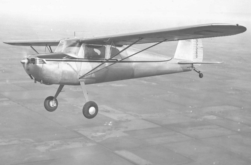
Cessna s/n 12403 left the factory 22 Jan 1947 as NC2167N.
The plane was sold to Hamburg Airpark Inc. of Hamburg, New York.
Sold 10 Mar 1947 to Robert Knoche of Hamburg, New York.
Sold 23 Oct 1948 to William Hauck of Buffalo, New York.
Sold 19 Feb 1949 to Kellogg Mann Jr. of Cleveland, Ohio.
Sold 27 Mar 1950 to Buffalo Aeronautical Corp. of Buffalo, New York.
Sold 04 Apr 1950 to Henry Holland of Buffalo, New York.
Sold 04 May 1951 to Joseph Byrne of Santa Fe, New Mexico.
Sold 30 Jun 1952 to Knoxville Flying Service, Inc. of Alcoa, Tennessee.
Sold 04 May 1954 to Nina Gibson of Knoxville, Tennessee.
Sold 29 Oct 1954 to Omar Midyett of East St. Louis, Illinois.
Sold 11 Dec 1954 to Associated Pilots of St. Louis, Inc. of Webster Groves, Missouri.
Sold 20 Sep 1955 to M. and S. Flying Club, Inc. of Hullsboro, Illinois.
Sold 15 Oct 1955 to Donald Albert of LaSalle, Illinois.
Sold 10 Oct 1956 to Aero Traders of Milan, Michigan.
Sold 23 Jan 1957 to C. F. Wible of Sebewaing, Michigan.
Sold 30 Jan 1960 to Leo Gutzmer of Saginaw, Michigan.
Sold 11 Apr 1960 to Wesley & Arleigh Beebe of Flushing, Michigan.
Sold 06 Jul 1964 to Jerry Floyd Auto Sales of Flushing, Michigan.
Sold 07 Jul 1964 to John Powers of Clawson, Michigan.
Sold 04 Mar 1983 to Edward Weeks of Flint, Michigan.
Registration Number Changed on 25 Oct 1983 to N140TW.
Sold 01 Dec 1986 to Dennis Harbin of Charlottesville, Virginia now in Louisa, Virginia.

Monday, October 26, 2009

Left wing

Inspected structure. Installed tank. Installed root braces. Replaced outboard drag wire per AD 48-25-03. Checked and set trammel, tightened wires and jamb nuts per SLN-27.

Sunday, October 25, 2009

Left wing Primer

Installed new fuel tank hat support pads. Then expoxied and primed all chromated surfaces fabric will contact.